An electrical connection mechanism for a light effect panel

A connection mechanism and panel technology, applied in connection, two-part connection device, computer peripheral equipment connector, etc., can solve problems such as poor operating experience, operator injury, and external equipment collision damage.

Active Publication Date: 2019-05-28
ZHENGZHOU YUNHAI INFORMATION TECH CO LTD
View PDF6 Cites 0 Cited by
  • Summary
  • Abstract
  • Description
  • Claims
  • Application Information

AI Technical Summary

Problems solved by technology

[0004] 1. The two-way electrical connection terminals are installed and disassembled through the direct plug-in method. During the operation of disassembling and installing the light effect panel, it is necessary to pull or push the panel with specific actions, so that the two-way electrical connection terminals can be clamped on the At the same time, the labor intensity of the operator is high (poor operating experience), and at the same time, it will cause damage to the energized connection terminal and affect the service life of the energized connection terminal;
[0005] 2. When the light effect panel is removed, the power connection terminals will be directly exposed to the outside, which will not only affect the appearance quality of IT equipment and light effect panels, but also the exposed power connection terminals will have the problem of damage caused by external equipment collision; at the same time , the exposed energized connection terminals will cause harm to the operators who pass by, and the safety hazard is great.

Method used


Image

  • An electrical connection mechanism for a light effect panel
  • An electrical connection mechanism for a light effect panel
  • An electrical connection mechanism for a light effect panel

Examples


Embodiment Construction

[0030] In order to make the object, technical solution and advantages of the present invention clearer, the present invention will be further described in detail below in conjunction with the accompanying drawings and embodiments. It should be understood that the specific embodiments described here are only used to explain the present invention, not to limit the present invention.

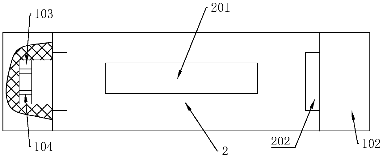
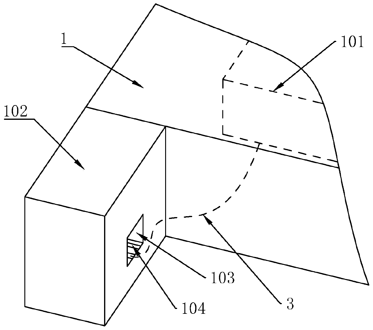
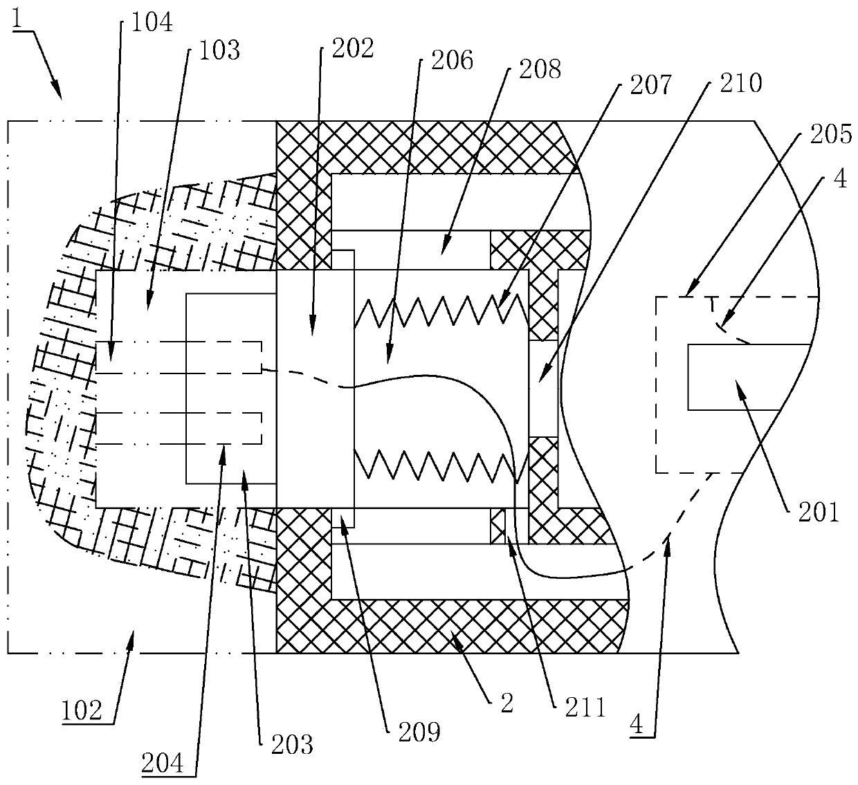
[0031] like Figure 1 to Figure 3As shown together, a power connection mechanism of a light effect panel includes a device main body 1. In this solution, the device body 1 is IT equipment such as a server and a memory, but the power connection mechanism of the light effect panel is not limited to be used in On IT equipment such as servers and storage devices; the device main body 1 is provided with a device circuit board 101 connected to the power supply, and both ends of the device main body 1 are provided with hanging ears 102, and the sides where the two hanging ears 102 are close to each other ...


PUM


Abstract

The invention discloses an energizing connection mechanism of a light effect panel. The energizing connection mechanism comprises a panel body and an equipment main body provided with an equipment circuit board, wherein lugs are arranged at two ends of the equipment main body; grooves are formed in the two lugs separately; at least one lug is provided with a first energizing contact which is electrically connected with the equipment circuit board and is located in the corresponding groove; buckles are arranged at two ends of the panel body and an elastic sliding mechanism is arranged between the buckles and the panel body; two buckles are provided with bumps; at least one bump is provided with a second energizing contact; and the second energizing contact is electrically connected with a panel circuit board in the panel body. The concealed and elastic clamping energization effects are achieved; disassembly and assembly operations are simple and convenient; time and labor are saved; thelabor intensity of operating personnel is greatly reduced; the appearance quality of a product and the man-machine operation experience are improved; and the work efficiency is effectively improved.In addition, the energizing connection mechanism is simple in structure, ingenious in design, good in connection effect, high in energizing stability and easy to maintain.

Description

technical field [0001] The invention relates to the technical field of IT equipment, in particular to an electrical connection mechanism for a light effect panel. Background technique [0002] As we all know, there are basically LOGO or decorative parts that need to be energized and illuminated on IT equipment such as servers and storage devices (the LOGO or decorative parts are set on the light effect panel). Both the panel and the IT equipment are equipped with power connection terminals, which are set on the front side, and the two power connection terminals are snapped together through the in-line method, thereby achieving the purpose of forming a circuit path and realizing the luminous LOGO or decorative parts . [0003] Adopt the mode described above, there is following defect: [0004] 1. The two-way electrical connection terminals are installed and disassembled through the direct plug-in method. During the operation of disassembling and installing the light effect ...

Claims


Application Information

Patent Timeline
Patent Type & Authority Patents(China)
IPC IPC(8): H01R24/00H01R13/02H01R13/46
CPCH01R13/02H01R13/46H01R24/005H01R2201/06
Inventor 林进献
Owner ZHENGZHOU YUNHAI INFORMATION TECH CO LTD
Why Eureka
Try Eureka