
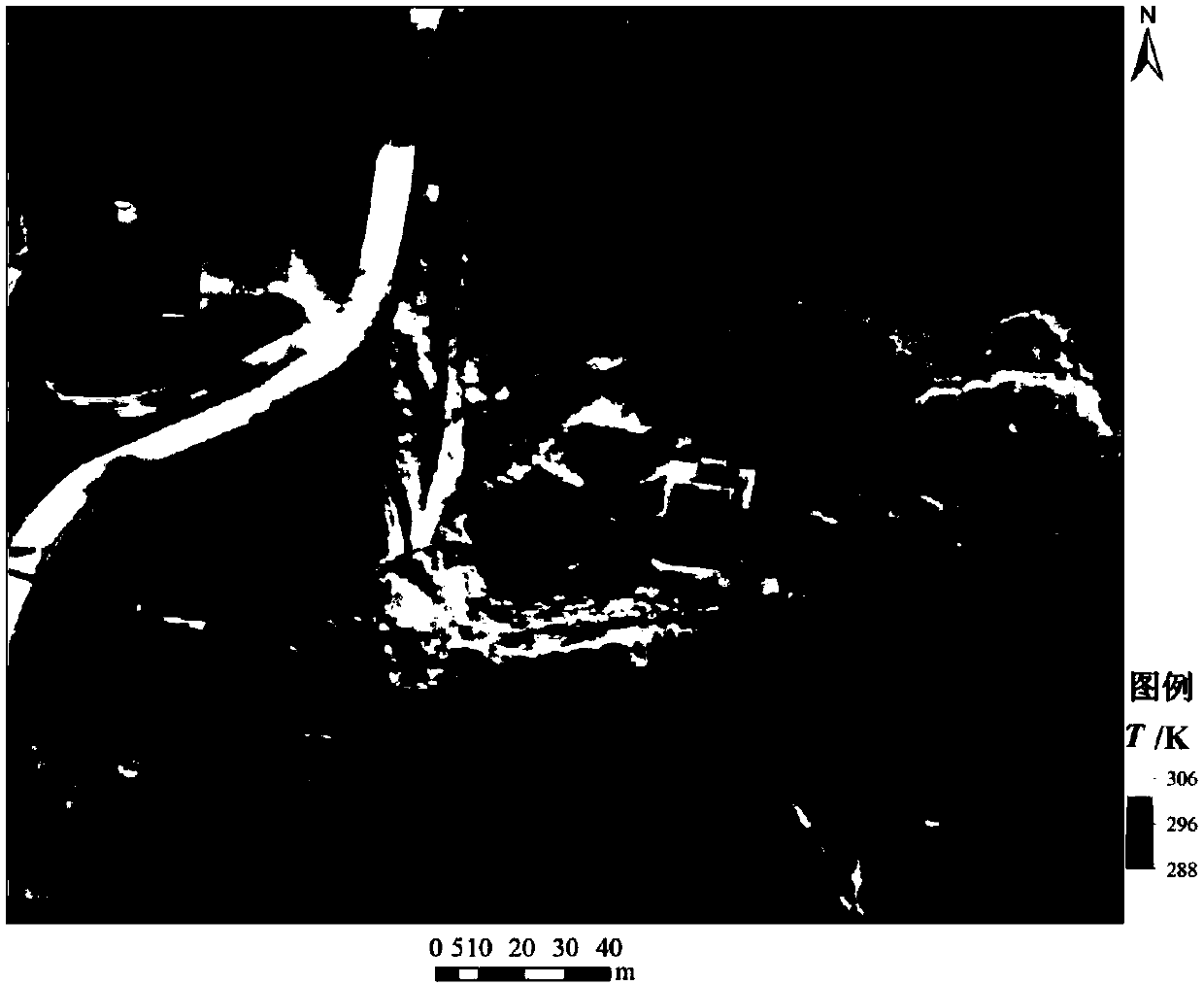
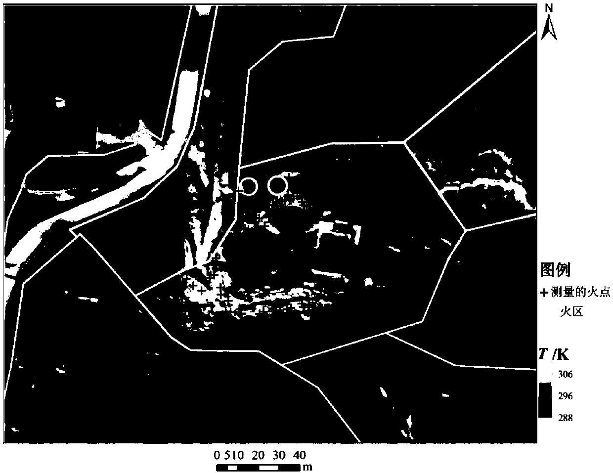
Drone thermal infrared image-based coal fire identification method

A recognition method, thermal infrared technology, applied in the field of coal fire recognition based on UAV thermal infrared images, can solve the problems of low precision, high cost of airborne thermal infrared detection of coal fires, low efficiency of coal fire recognition, etc., to improve efficiency effect

Active Publication Date: 2018-03-27
INST OF DISASTER PREVENTION
View PDF4 Cites 16 Cited by
  • Summary
  • Abstract
  • Description
  • Claims
  • Application Information

AI Technical Summary

Problems solved by technology

There are many methods for identifying coal fires, including geochemical methods, electric field methods, and geomagnetic methods. Although these methods have high detection accuracy, they need to go deep into the scene, which is dangerous and low in coal fire identification efficiency.
At present, it is common to use remote sensing methods to establish surface thermal fields to identify coal fires, but the accuracy of satellite thermal infrared remote sensing identification methods is low [3] , the cost of airborne thermal infrared detection of coal fires is too high, these reasons greatly limit the development of coal fire thermal infrared remote sensing coal fire detection technology [4] , there is an urgent need for a rapid coal fire identification method with low cost and high detection accuracy

Method used


Image

  • Drone thermal infrared image-based coal fire identification method
  • Drone thermal infrared image-based coal fire identification method
  • Drone thermal infrared image-based coal fire identification method

Examples


Embodiment Construction

[0047] The present invention will be further described below through specific embodiments and accompanying drawings. The embodiments of the present invention are for better understanding of the present invention by those skilled in the art, and do not limit the present invention in any way.

[0048] The coal fire identification method based on the thermal infrared image of the UAV, the specific steps are as follows:

[0049] 1) UAV thermal infrared image acquisition:

[0050] Assemble the thermal infrared camera (FLIR TAU 324), circuit board, special battery for drones, and GPS antenna into one, and install them in the drone platform. The drone is preferably a rotor drone. The thermal infrared image acquisition process is always Keep the lens of the thermal infrared camera facing the ground vertically, and at the same time ensure that the longer format of the thermal infrared camera is perpendicular to the flying direction of the drone.

[0051]According to the topography of...


PUM


Abstract

The invention discloses a drone thermal infrared image-based coal fire identification method. The method mainly comprises the following steps that: a thermal infrared camera is mounted on a rotor drone pan-tilt holder, and a drone completes the acquisition work of the thermal infrared images of a mine area according to a designed flight route; the acquired thermal infrared images are preprocessed;the thermal infrared camera is calibrated through a laboratory black body radiator, the DN values of the images are converted into apparent radiance values; all the thermal infrared images are subjected to aerial triangulation adjustment orienteering, and a thermal infrared orthoimage is obtained through mosaic, and the surface temperature of the mining area is obtained through inversion on the basis of an atmospheric transport equation and the Planck function; and a high gradient graph is generated according to the Sobel edge operator, the high gradient graph is refined into skeleton lines,a high temperature area and the high gradient lines are superimposed, the temperature average value of the overlapping position of the high temperature area and the high gradient lines is adopted as the fire area segmentation threshold value of the mining area, and the threshold value is adopted to identify the coal fire area of the mining area. The coal fire identification accuracy of the methodcan be as high as 96.7%. With the method of the invention adopted, the rapid and accurate identification and drawing of coal fires under the conditions of complex mining areas can be realized at relatively low cost.

Description

technical field [0001] The invention relates to the field of UAV airborne thermal infrared imaging detection, in particular to a coal fire identification method based on UAV thermal infrared images. Background technique [0002] Coal fire is a spontaneous combustion phenomenon caused by long-term oxidation, which often occurs in underground coal seams, open pit coal mines, coal piles, etc. Spontaneous combustion of coal has seriously affected natural resources, the ecological environment, and the health of residents. Coal has low mining cost and is easy to store and transport. As the main energy raw material, it accounts for about 30% of the total energy consumption [1] . As a big country in coal mining and use, China's coal consumption accounts for about 70% of the country's energy. According to statistics, there are 56 coalfield fire areas in northern China, with an area of ​​720km2. 2 , the annual loss of coal combustion reaches 20 million tons, and the coal resources ...

Claims


Application Information

Patent Timeline
IPC IPC(8): G01V8/10H04N5/33
CPCG01V8/10H04N5/33
Inventor 李峰卫爱霞
Owner INST OF DISASTER PREVENTION
Learn More