
Cooling system for shaft system of wind driven generator and wind generating set

A technology of wind power generating set and cooling system, which is applied in the direction of wind power motor combination, wind power engine, wind power generation, etc. It can solve problems such as dry friction, impact on bearing life, temperature rise of parts, etc., achieve reliable installation and operation, and improve heat dissipation efficiency , The effect of simple heat pipe structure

Pending Publication Date: 2018-03-27
BEIJING GOLDWIND SCI & CREATION WINDPOWER EQUIP CO LTD
View PDF7 Cites 8 Cited by
  • Summary
  • Abstract
  • Description
  • Claims
  • Application Information

AI Technical Summary

Problems solved by technology

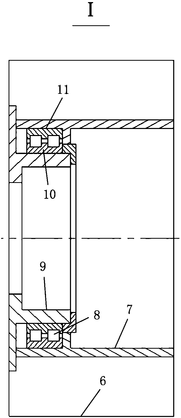
If the generated heat cannot be dissipated in real time, the bearing will have a higher temperature, and the higher temperature will cause the viscosity of the lubricating oil to decrease, which will affect the bearing inner ring 10, bearing roller 8 and bearing outer ring of the bearing. 11 The lubricating oil film between each other is established, which may cause dry friction, resulting in a sharp rise in the temperature of the components inside the transmission system, the working clearance of the main bearing will exceed the reasonable working range due to thermal expansion, and even "shaft holding" may occur "Phenomenon
It can be seen that long-term high-temperature operation will lead to a serious vicious cycle, and seriously affect the life of the bearing, resulting in failure of the bearing, which cannot meet the 20-25-year operating life requirement of the wind turbine.

Method used


Image

  • Cooling system for shaft system of wind driven generator and wind generating set
  • Cooling system for shaft system of wind driven generator and wind generating set
  • Cooling system for shaft system of wind driven generator and wind generating set

Examples


Embodiment Construction

[0035] Embodiments of the present invention will be specifically described below in conjunction with the accompanying drawings.

[0036] In the following, the main bearing of the wind power generating set will be described as the cooling object, but it should be noted that the present invention is not limited thereto, and the cooling system according to the exemplary embodiment can also be applied to other shafting of the wind power generating set. In addition, descriptions about directions are based on the shape of the main bearing, for example, descriptions such as "inside", "outside" and "inner surface" and "inner surface" are based on the radial direction of the main bearing, specifically , the surface closest to the central axis of the main bearing and facing the central axis is the "inner surface" or "inner surface", and vice versa is the "outer surface" or "outer surface".

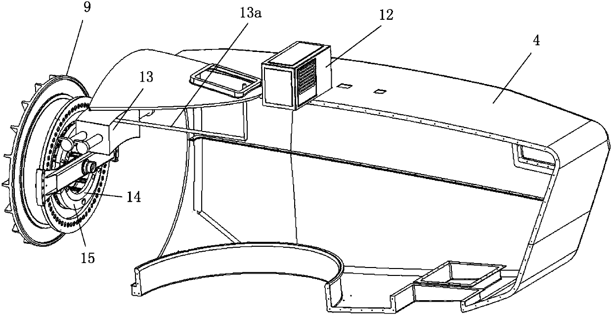
[0037] image 3 It is a partially cut-away and exploded schematic diagram of a wind power gener...


PUM


Abstract

The invention provides a cooling system for a shaft system of a wind driven generator and a wind generating set. The cooling system comprises a cold air supply unit, an air feeding tank coaxially fixed onto a fixed shaft, an air return tank coaxially fixed onto the fixed shaft, and an annular heat-radiating assembly fixedly arranged on an inner surface of a rotary shaft, wherein cold air from thecold air supply unit is supplied to the annular heat-radiating assembly through the air feeding tank, and air subjected to heat exchange with the annular heat-radiating assembly is returned into the cold air supply unit through the air return tank. Through arranging the cooling system provided by the invention, the temperature of the shaft system of the wind generating set can be reduced to a reasonable running range, so that the service life of the shaft system is ensured, and the reliability in running the wind generating set is ensured.

Description

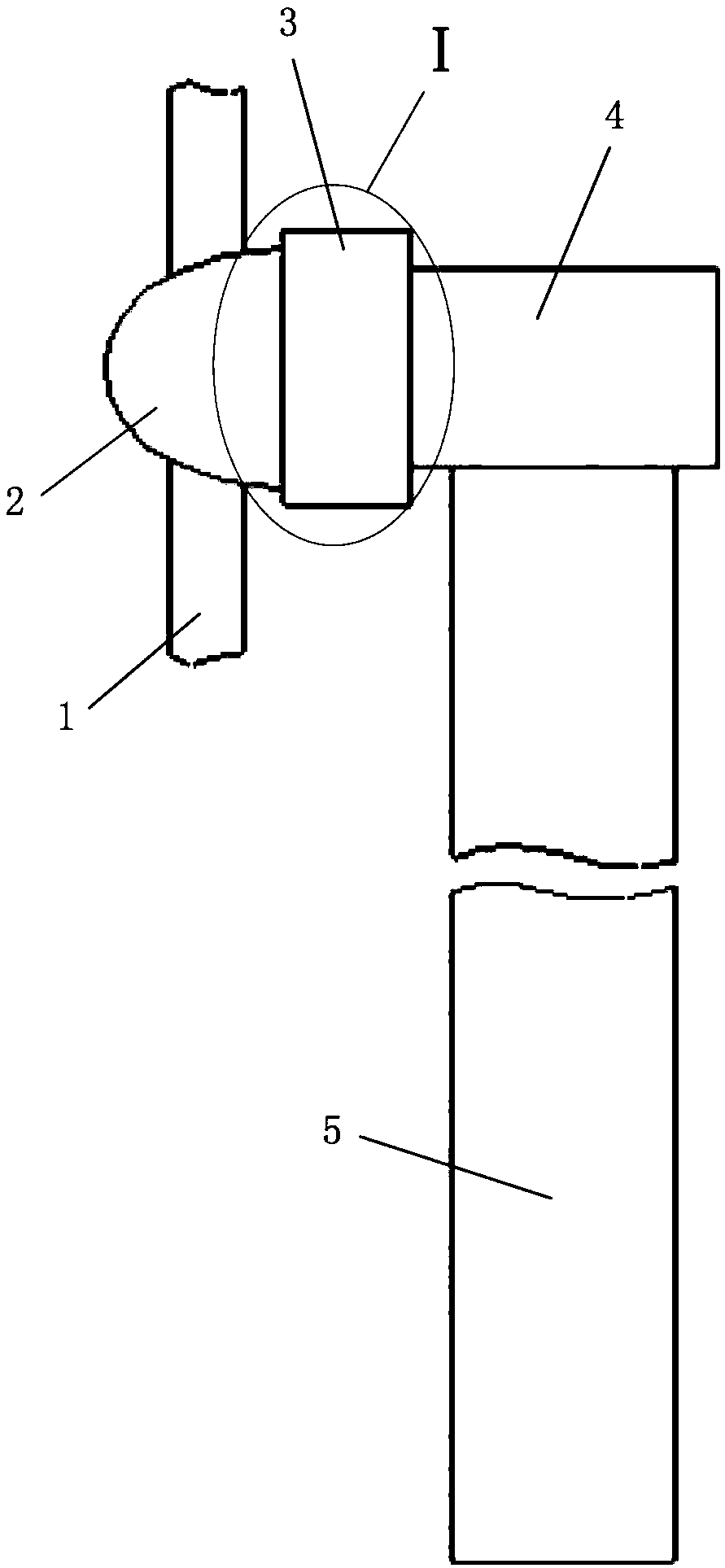
technical field [0001] The invention relates to the field of wind power generation, in particular to a cooling system for a shaft system of a wind power generator and a wind power generating set including the cooling system. Background technique [0002] Most wind turbines use permanent magnet direct drive wind turbines. Such as figure 1 and figure 2 ( figure 1 is a schematic diagram of the structure of a wind turbine, figure 2 yes figure 1 As shown in the sectional view of part I of ), the wind turbine with permanent magnet direct drive wind generator mainly includes: blade 1, hub 2, generator subsystem 3, nacelle 4 and tower 5. The generator subsystem 3 mainly includes: a permanent magnet direct drive wind turbine 6, a fixed shaft 7, a rotating shaft 9, and a main bearing. Main bearing comprises bearing inner ring 10, bearing roller 8 and bearing outer ring 11, and bearing inner ring 10 is connected to rotating shaft 9, and bearing outer ring 11 is connected to fix...

Claims


Application Information

Patent Timeline
Patent Type & Authority Applications(China)
IPC IPC(8): F03D80/60F03D80/70F03D9/25
CPCF03D9/25F03D80/60F03D80/70Y02E10/72
Inventor 高杨白洛林邢赢方涛梁坤峰
Owner BEIJING GOLDWIND SCI & CREATION WINDPOWER EQUIP CO LTD
Learn More