
Product positioning mechanism and abrasive blasting mechanism

A technology of positioning mechanism and product structure, applied in abrasive jet machine tools, metal processing equipment, manufacturing tools, etc., can solve the problems of unsatisfactory product sandblasting effect, low product production efficiency, cumbersome operation, etc., to improve sandblasting quality and The effect of production efficiency, convenient operation and simple overall structure

Active Publication Date: 2018-03-27
GEER TECH CO LTD
View PDF5 Cites 0 Cited by
  • Summary
  • Abstract
  • Description
  • Claims
  • Application Information

AI Technical Summary

Problems solved by technology

[0004] In view of the above problems, the purpose of the present invention is to provide a product positioning mechanism and a sandblasting mechanism to solve the problems of cumbersome operation of product sandblasting operation, unsatisfactory product sandblasting effect, resulting in low production efficiency and poor quality of products.

Method used


Image

  • Product positioning mechanism and abrasive blasting mechanism
  • Product positioning mechanism and abrasive blasting mechanism
  • Product positioning mechanism and abrasive blasting mechanism

Examples


Embodiment Construction

[0026] In the following description, for purposes of explanation, numerous specific details are set forth in order to provide a thorough understanding of one or more embodiments. It may be evident, however, that these embodiments may be practiced without these specific details. In other instances, well-known structures and devices are shown in block diagram form in order to facilitate describing one or more embodiments.

[0027] In order to describe the structure of the product positioning mechanism of the present invention in detail, specific embodiments of the present invention will be described in detail below in conjunction with the accompanying drawings.

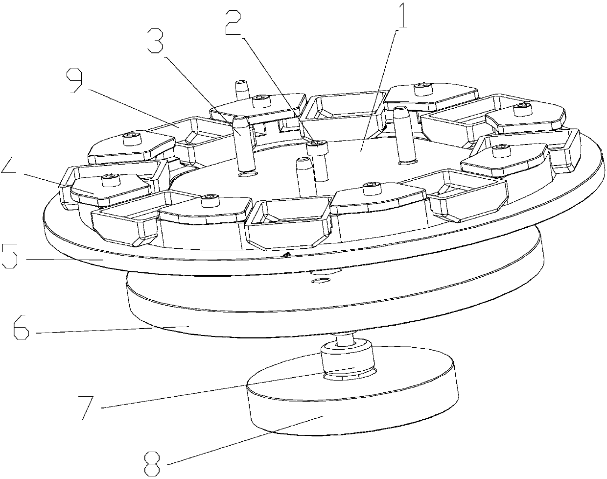
[0028] figure 1 An exploded structure of a product positioning mechanism according to an embodiment of the invention is shown.

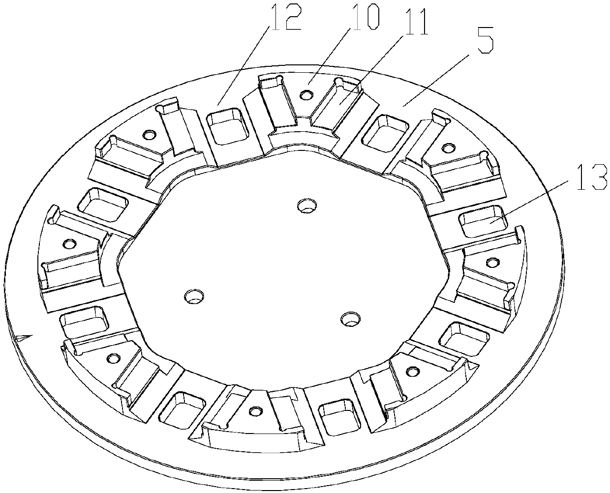
[0029] like figure 1 As shown, the product positioning mechanism of the embodiment of the present invention includes a circular base 6, a circular fixed plate 5 and a bearing 7 that are res...


PUM


Abstract

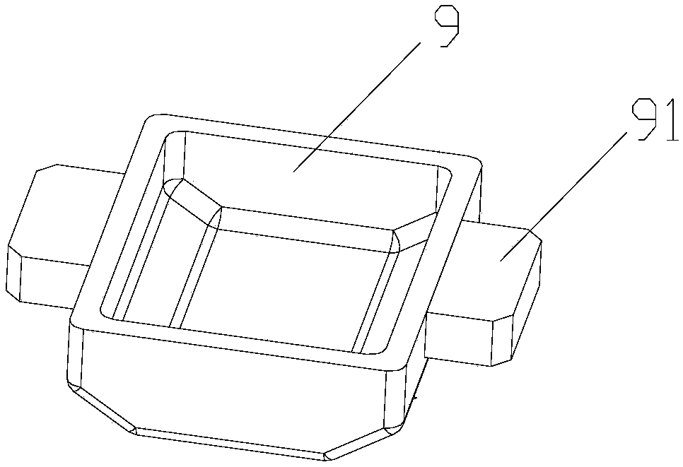
The invention provides a product positioning mechanism and an abrasive blasting mechanism. The positioning mechanism comprises a round base, a fixing plate and a bearing, wherein the fixing plate andthe bearing are arranged on the upper side and the lower side of the base correspondingly; the fixing plate rotates around the bearing; a detachable baffle is arranged in the center of the fixing plate; product limiting platforms and limiting cover plates covering the product limiting platforms are evenly distributed on the fixing plate; a product limiting groove matched with a product to be positioned in structure is formed between every two adjoining product limiting platforms; and the products to be positioned are arranged in the product limiting grooves and limited with the assistance of the limiting cover plates and the baffle. Through the product positioning mechanism and the abrasive blasting mechanism, the multiple products can be positioned at the same time, one-time uniform abrasive blasting operation of the products is realized, and the risk of sand accumulation is reduced.

Description

technical field [0001] The invention relates to the technical field of product processing, more specifically, to a product positioning mechanism and a product sandblasting mechanism provided with the product positioning mechanism. Background technique [0002] For sandblasting and deburring of metal workpieces, the existing technology mainly fixes metal products directly on the profiling fixtures such as jigs and plates, and then sandblasts the fixed products. This kind of fixing method can only It is applied to the processing of samples or a small amount of metal products, and the loading and unloading operations of the products are cumbersome and time-consuming. During the continuous sandblasting process of the products, it is easy to cause sand accumulation in the grooves inside the products, resulting in metal products Sandblasting is not uniform in some parts of the area, and secondary sandblasting is required, resulting in a serious waste of time, cost and manpower, an...

Claims


Application Information

Patent Timeline
Patent Type & Authority Applications(China)
IPC IPC(8): B24C3/20B24C3/00
CPCB24C3/00B24C3/20
Inventor 程品回燕华程宝
Owner GEER TECH CO LTD
Learn More