
Hybrid direct-current solid state circuit breaker and control method thereof

A solid-state circuit breaker and hybrid technology, applied in circuit devices, emergency protection circuit devices, emergency protection devices with automatic disconnection, etc., can solve problems such as high-voltage spikes of absorbing capacitors and increased short-circuit current, and achieve self-discharge to ensure safety Effect

Active Publication Date: 2018-03-23
WUHAN MARINE ELECTRIC PROPULSION RES INST CHINA SHIPBUILDING IND CORP NO 712 INST
View PDF7 Cites 8 Cited by
  • Summary
  • Abstract
  • Description
  • Claims
  • Application Information

AI Technical Summary

Problems solved by technology

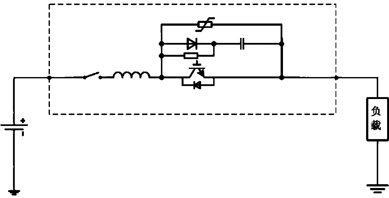
[0004] The power electronic device in the DC solid-state circuit breaker is in the conduction state when it is working normally, the capacitor in the RCD absorbing circuit has no initial energy, and the power electronic device is turned off when the short circuit occurs, the RCD circuit provides an additional short-circuit channel, which will lead to an increase in the short-circuit current; The short-circuit current will also cause a high voltage peak on the absorption capacitor, so the DC solid-state circuit breaker that usually uses RCD absorption needs to be protected by connecting a varistor in parallel with the absorption circuit. For the implementation circuit, see figure 1 shown

Method used


Image

  • Hybrid direct-current solid state circuit breaker and control method thereof
  • Hybrid direct-current solid state circuit breaker and control method thereof
  • Hybrid direct-current solid state circuit breaker and control method thereof

Examples


Embodiment Construction

[0022] The present invention will be described in further detail below in conjunction with the accompanying drawings.

[0023] In order to overcome the deficiencies of existing DC solid-state circuit breakers, the purpose of the present invention has two points:

[0024] 1. Limit the additional short-circuit current and the voltage spikes caused by the absorption circuit when the power electronic device in the DC solid-state circuit breaker is turned off.

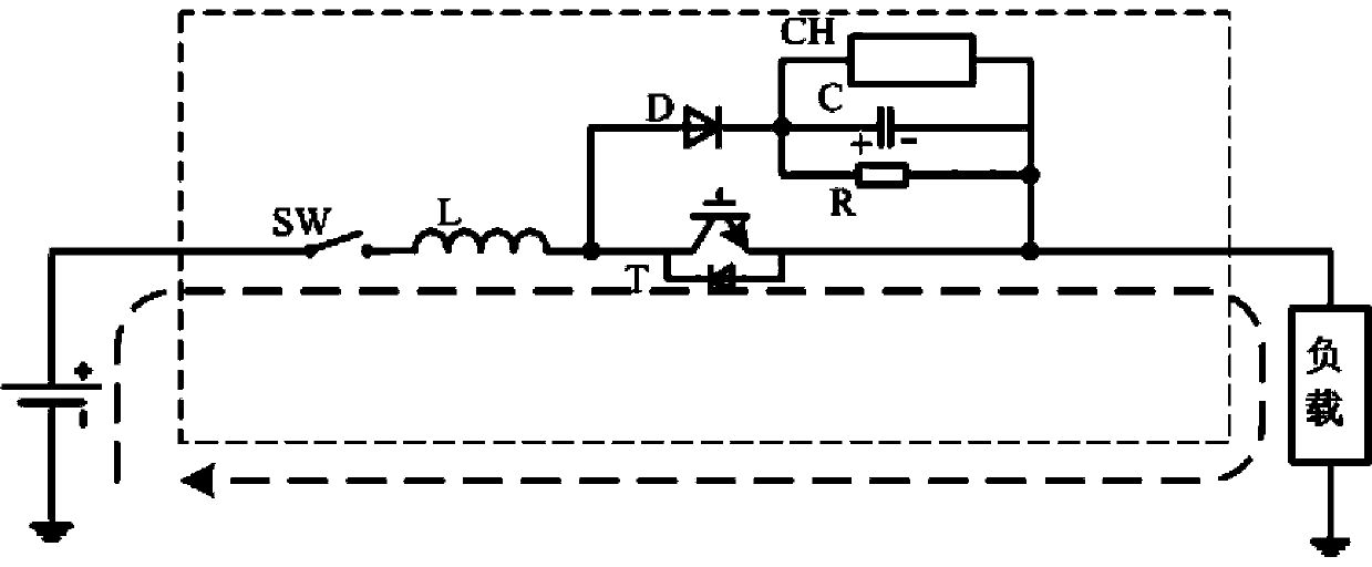
[0025] 2. Through the control system in the DC solid-state circuit breaker, according to the control method of the present invention, the internal semiconductor device and the absorbing capacitor voltage stabilization device are turned on and off to complete the breaking of the fault current, the safety isolation of the equipment, and the shutdown energy discharge of the absorbing capacitor.

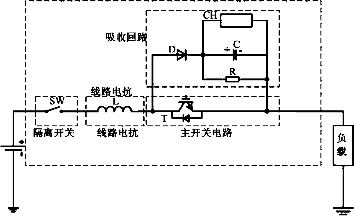
[0026] A hybrid DC solid-state circuit breaker disclosed by the present invention includes an isolating switch SW, a current limitin...


PUM


Abstract

The invention discloses a hybrid direct-current solid state circuit breaker. The hybrid direct-current solid state circuit breaker comprises an isolating switch SW, a circuit reactor L, a main switchcircuit T, an absorption circuit and a control system; one end of the isolating switch SW is connected with an external direct current power supply, and the other end of the isolating switch SW is connected with the circuit reactor L; the main switch circuit T is composed of a semiconductor device T1; a positive end of the semiconductor device T1 is connected with the circuit reactor L, and a negative end of the semiconductor device T1 is connected with an external load; the absorption circuit consists of a diode D, an absorption capacitor C, an absorption capacitor voltage stabilizing deviceCH and an energy discharge resistor R; and the control system includes a current detection unit and a signal processing unit. The invention further discloses a control method of the hybrid direct-current solid state circuit breaker. According the hybrid direct-current solid state circuit breaker and the control method thereof, the absorption capacitor voltage stabilizing device is adopted to preset an absorption capacitor voltage, so an additional short-circuit current generated by an absorption loop and a voltage spike on the absorption capacitor when the semiconductor device is turned off are effectively limited; and after the absorption capacitor voltage stabilizing device stops to work, the self discharge can be implemented by the system to guarantee the safety.

Description

technical field [0001] The invention belongs to the technical field of power electronic equipment and DC power distribution system fault protection, and in particular relates to a hybrid DC solid-state circuit breaker realized by using power electronic devices, and a control method thereof. Background technique [0002] In the DC power distribution system, once a short-circuit fault occurs in the system, the power supply or other capacitive equipment connected to the grid will feed power to the fault point. When the protection device operates for a long time, a large short-circuit current will be generated. At the same time, the capacitive equipment The rapid discharge of the DC voltage will cause the DC voltage to drop rapidly and fail protection will occur, resulting in the failure of the device to work. [0003] Mechanical circuit breakers are often used for protection in traditional DC power distribution systems, but their action time is long, and it often takes tens or ...

Claims


Application Information

Patent Timeline
IPC IPC(8): H02H7/26H02H3/02
CPCH02H3/025H02H7/268
Inventor 刘念洲许晓晖槐博超陈雪亮赵晓宇
Owner WUHAN MARINE ELECTRIC PROPULSION RES INST CHINA SHIPBUILDING IND CORP NO 712 INST
Learn More