
Micro gyroscope adaptive high-order super-twist slip form control method

A technology of micro-gyroscope and control method, applied in adaptive control, general control system, control/regulation system and other directions, can solve the problems of reduced sensitivity and accuracy of gyroscope system, inability to accurately implement control law, inability to accurately obtain and other problems

Inactive Publication Date: 2018-03-23
HOHAI UNIV CHANGZHOU
View PDF9 Cites 12 Cited by
  • Summary
  • Abstract
  • Description
  • Claims
  • Application Information

AI Technical Summary

Problems solved by technology

Because of the influence of errors and temperature in design and manufacturing, it will lead to differences between the characteristics of the original and the design, resulting in a decrease in the sensitivity and accuracy of the gyroscope system. The main problem of micro gyroscope control is to compensate for manufacturing errors and measure angular velocity
After decades of research and development, micro gyroscopes have made significant progress in terms of structural design and precision, but due to the limitations of their design principles and the limitations of process precision, the development of micro gyroscopes is difficult to achieve. Great progress
[0003] The measurement of angular velocity and the compensation of manufacturing errors are the main problems of micro-gyroscope control. However, because the traditional control method mainly solves the problem of stable control of the oscillation amplitude and frequency of the drive shaft and the matching of the frequency of the two axes, it cannot effectively solve the problems of micro-gyroscopes. deficiencies and defects
[0004] And for the actual micro-gyroscope system, the three parameters D, K, and Ω in the dimensionless model of the micro-gyroscope are unknown or cannot be obtained accurately, so the designed control law cannot be accurately implemented when the control is implemented. Therefore, it is very important to identify the unknown parameters of the micro gyroscope.

Method used


Image

  • Micro gyroscope adaptive high-order super-twist slip form control method
  • Micro gyroscope adaptive high-order super-twist slip form control method
  • Micro gyroscope adaptive high-order super-twist slip form control method

Examples


Embodiment Construction

[0075] The present invention will be further described below. The following examples are only used to illustrate the technical solution of the present invention more clearly, but not to limit the protection scope of the present invention.

[0076] 1. Mathematical model of micro gyroscope:

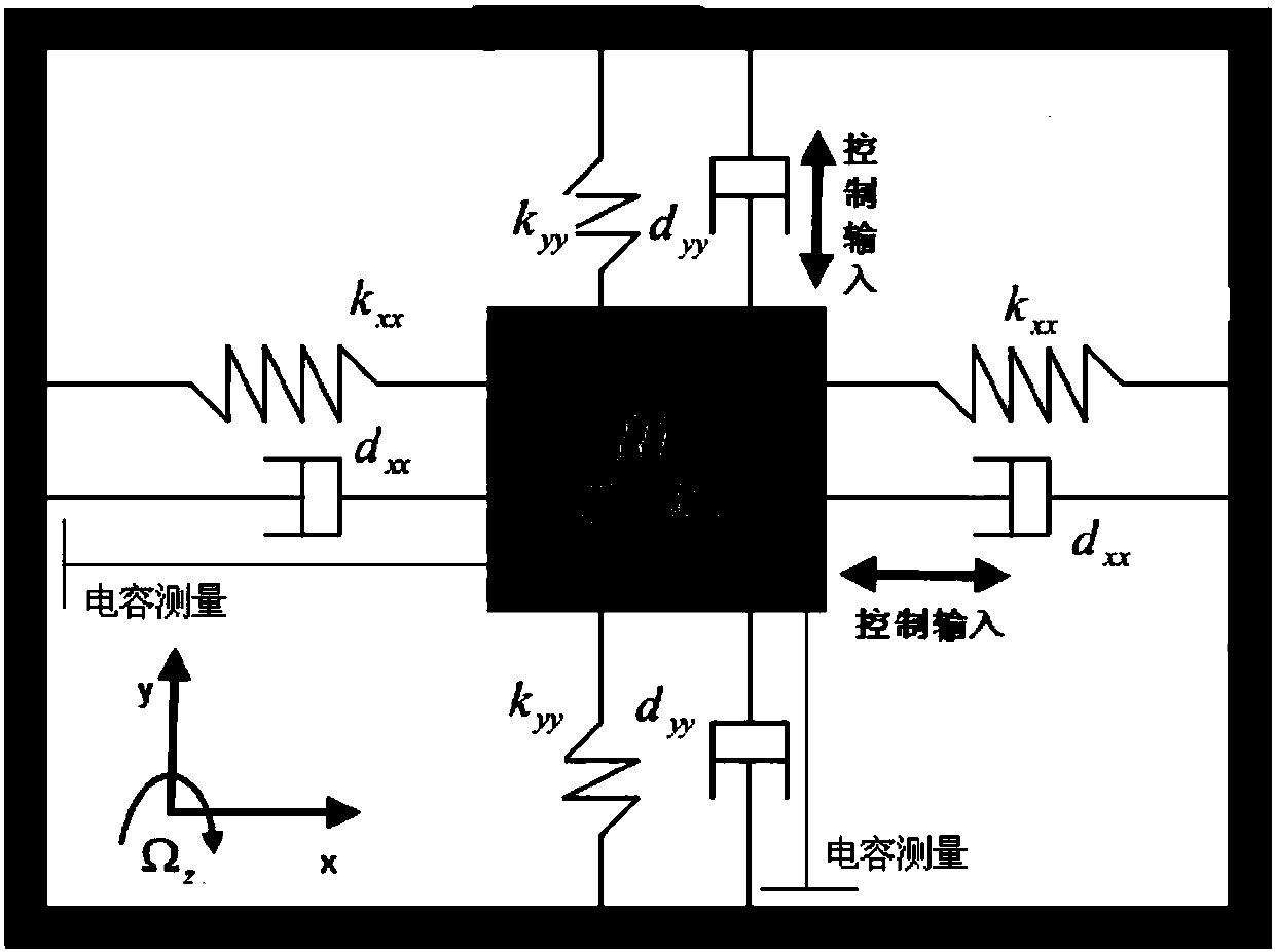
[0077] A micro-vibration gyroscope usually consists of three parts: a mass suspended by an elastic material support, an electrostatic drive device, and a sensing device. This can be simplified as figure 1 A damped oscillatory system consisting of a mass and a spring is shown, which shows a simplified z-axis micromechanical vibratory gyroscope model in Cartesian coordinates.

[0078] According to Newton's law in the rotating system, comprehensively considering the influence of various manufacturing errors on the micro-gyroscope, and then through the dimensionless processing of the micro-gyroscope, the mathematical model of the micro-gyroscope is finally obtained as follows:

[0079]

...


PUM


Abstract

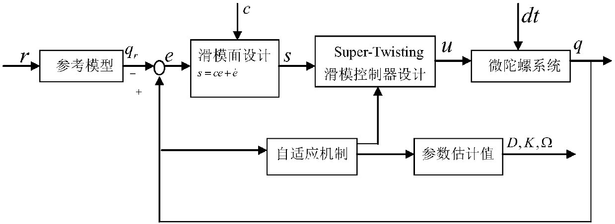
The present invention discloses a micro gyroscope adaptive high-order super-twist slip form control method. The micro gyroscope adaptive high-order super-twist slip form control method adopts a methodof combining the equivalent slip form control and the super-twist control to design an adaptive high-order super-twist slip form controller and design the adaptive laws of which the parameters are not determined of a micro gyroscope system, and then adopts an Lyapunov function to analyze the stability of the micro gyroscope system, thereby guaranteeing the asymptotic stability of the system. Themethod of the present invention combines the advantages that the high-order super-twist slip form control can effectively suppresses the buffeting, etc., controls to improve the performances of the system, enables the robustness of the micro gyroscope system to the indeterminacy and the external interference to be improved, and guarantees the stability of the system.

Description

technical field [0001] The invention relates to a micro-gyroscope self-adaptive high-order super-twist sliding mode control method, which belongs to the technical field of micro-gyroscope control. Background technique [0002] Gyroscopes are the basic measurement elements of inertial navigation and inertial guidance systems. Because of its huge advantages in cost, volume, and structure, micro gyroscopes are widely used in civil and military fields such as navigation, aerospace, aviation, and oil field survey and development, and land vehicle navigation and positioning. Because of the influence of errors and temperature in design and manufacturing, it will lead to differences between the characteristics of the original and the design, resulting in a decrease in the sensitivity and accuracy of the gyroscope system. The main problem of micro gyroscope control is to compensate for manufacturing errors and measure angular velocity . After decades of research and development, mi...

Claims


Application Information

Patent Timeline
IPC IPC(8): G05B13/04
CPCG05B13/042
Inventor 冯治琳费峻涛王欢
Owner HOHAI UNIV CHANGZHOU
Learn More