Eureka AIR delivers breakthrough ideas for toughest innovation challenges, trusted by R&D personnel around the world.

Polarization-based visible light positioning method and hardware system thereof

A positioning method and hardware system technology, applied in the field of visible light communication, can solve the problems of increased construction cost and system implementation burden, and achieve the effects of precise video frame time, strong communication reliability, and low pulse rate

Pending Publication Date: 2018-03-23
SOUTH CHINA UNIV OF TECH
View PDF10 Cites 14 Cited by
  • Summary
  • Abstract
  • Description
  • Claims
  • Application Information

AI Technical Summary

Problems solved by technology

[0004] In the existing visible light positioning system based on intensity modulation, considering the flickering effect of light intensity caused by atmospheric turbulence, the transmitting end needs to provide high-speed pulses to avoid the adverse effects caused by strong light flickering, so the receiving end of the system needs quite complicated equipment to meet For the detection and reception of high-rate pulses, the construction cost of the system increases and brings a serious burden to the realization of the system

Method used


Image

  • Polarization-based visible light positioning method and hardware system thereof
  • Polarization-based visible light positioning method and hardware system thereof
  • Polarization-based visible light positioning method and hardware system thereof

Examples


Embodiment

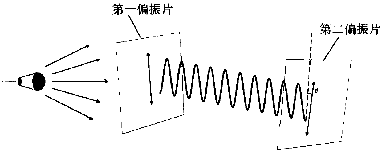
[0038] Please refer to figure 1 , the present invention is based on the polarization modulation technology, and the light source generates polarized light beams of different colors and different polarization directions through the VLC transmitting end. The VLC transmitter consists of three parts: the first polarizer (linear polarizer), the liquid crystal layer, and the disperser. The first polarizer at the sending end converts the unpolarized light emitted by the lamp into polarized light, performs binary color shift keying (BCSK) modulation on the polarized light through the liquid crystal layer, and disperses the polarized light emitted by the liquid crystal layer into different colors through the dispersion device of polarized light. At the receiving end, the polarization change of light cannot be directly captured by the camera. The light beam first passes through the second polarizer and only passes through one beam of polarized light to filter out the rest of the light ...


PUM


Abstract

The present invention discloses a polarization-based visible light positioning method and a hardware system thereof. Based on a polarization modulation technology, a light beam emitted out by a lamp generates the polarized light beams of different colors and different polarization directions via an emission end, a first polaroid at the emission end converts the non-polarized light emitted out by the lamp into the polarized light, a liquid crystal layer carries out the binary color shift keying (BCSK) modulation on the polarized light, and a dispersor disperses the polarized light emitted out by the liquid crystal layer into the polarized light of different colors. At a reception end, the light beam passes a second polaroid, only one beam of polarized light passes, the polarized light of other directions are filtered, and the polarization change of the light is transformed into the brightness change, thereby being captured by an image device accurately. By combining a camera-based angleof arrival (AOA) positioning algorithm, the higher-precision positioning is realized. According to the present invention, the calculation difficulty of the system can be reduced, the visible light positioning precision is improved, and the polarization-based visible light positioning method and the hardware system thereof are suitable for the electronic mobile terminal equipment, such as the intelligent mobile phones, the tablet personal computers, the Google glasses, etc.

Description

technical field [0001] The present invention relates to the technical field of visible light communication, in particular to a polarization-based visible light positioning method and a hardware system thereof. Background technique [0002] Visible light communication is a technology that can build a wireless communication network by adding data transmission functions to basic public lighting facilities. Compared with traditional wireless communication technology, visible light communication technology has rich bandwidth resources, is free from electromagnetic interference, and takes into account both lighting and positioning. Etc. [0003] Due to the influence of multipath effect and path loss, traditional GPS navigation and positioning cannot meet people's requirements for positioning accuracy. Therefore, a series of indoor positioning systems based on Bluetooth, WIFI, ultrasound, and infrared have appeared, but due to the problems of positioning accuracy and installation ...

Claims


Application Information

Patent Timeline
IPC IPC(8): G01S5/16H04B10/116
CPCH04B10/116G01S5/16Y02D30/70
Inventor 吴玉香关伟鹏刘晓伟方良韬谢灿宇
Owner SOUTH CHINA UNIV OF TECH
Why Eureka
Eureka Blog
Learn More