
Debugging device for integrated servo valve

A technology of servo valve and debugging board, which is applied in the direction of fluid pressure actuation device, fluid pressure actuation system test, mechanical equipment, etc., to achieve the effect of improving stability and reliability

Active Publication Date: 2018-03-23
SHANGHAI HENGTUO HYDRAULIC CONTROL TECH
View PDF6 Cites 2 Cited by
  • Summary
  • Abstract
  • Description
  • Claims
  • Application Information

AI Technical Summary

Problems solved by technology

[0002] At present, the debugging of the integrated servo valve can only use a single debugging, and it is impossible to jointly debug another servo valve after the debugging of a single servo valve is completed.

Method used


Image

  • Debugging device for integrated servo valve
  • Debugging device for integrated servo valve
  • Debugging device for integrated servo valve

Examples


Embodiment Construction

[0015] The present invention will be further described below in conjunction with the accompanying drawings and embodiments.

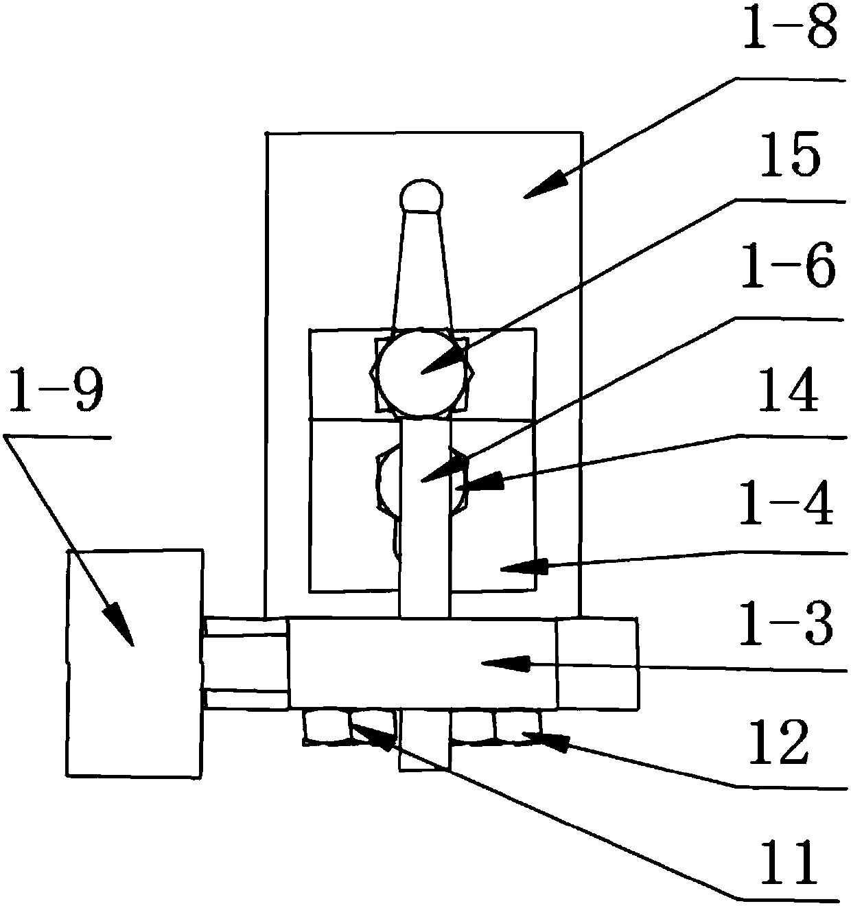
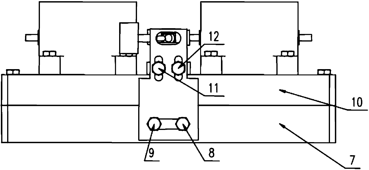
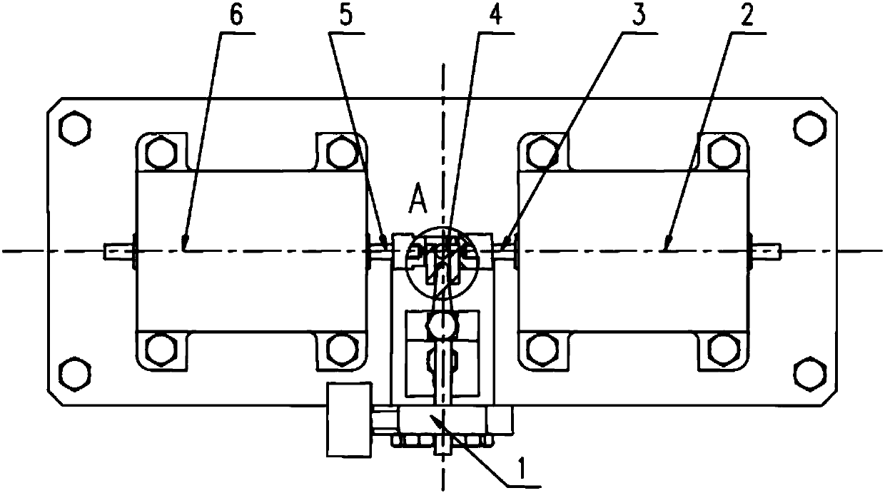
[0016] Such as figure 1 As shown, the integrated servo valve debugging device of the present invention is mainly composed of screw three 11, screw four 12, connecting plate 1-3, clamping block 1-4, screw five 14, loading rod 1-6, screw six 15, load Plate 1-8, limit screw rod 1-9 form. Screws three 11 and screws four 12 connect the connection plate 1-3 with the load plate 1-8, and by adjusting the screws three 11 and screws four 12, the connection plate 1-3 moves in the vertical direction. Screw six 15 connects the loading rod 1-6 with the clamping block 1-4, and drives the loading rod 1-6 to move by adjusting the front and rear positions of the clamping block 1-4. Screw five 14 connects the clamping block 1-4 with the load plate 1-8. Limit screw 1-9 can adjust and fix the position of loading rod 1-6.

[0017] Such as Figure 2 to Figure 4 As shown,...


PUM


Abstract

The invention relates to a debugging device for an integrated servo valve. The debugging device comprises a connecting plate, a clamping block, a loading bar, a loaded plate and a limiting screw, wherein the connecting plate is connected to the loaded plate through screws and can move in the vertical direction along the screws; the clamping block is connected to the loaded plate and connected withthe loading bar through screws; the loading bar can be driven by the clamping block to move back and forth; the rear end of the loading bar extends into a long waist hole in the upper part of the connecting plate and is in contact connection with the limiting screw on the side surface of the connecting plate; and the left-right position of the loading bar can be adjusted and set through the limiting screw. Technical parameters of a four-redundant servo valve debugged by the debugging device still meet the requirements of related standards and technical protocols after such tests of high-low-temperature circulation and vibration.

Description

technical field [0001] The invention relates to an electro-hydraulic servo control element in hydraulic engineering, in particular to an integrated servo valve debugging device. Background technique [0002] At present, the debugging of the integrated servo valve can only use a single debugging, and it is impossible to jointly debug another servo valve after the debugging of a single servo valve is completed. Therefore, it is necessary to design an integrated servo valve debugging device to meet the joint debugging requirements of the integrated servo valve. Contents of the invention [0003] The present invention provides an integrated servo valve debugging device to meet the joint debugging requirements of the integrated servo valve. [0004] To achieve the above object, the technical solution of the present invention is: an integrated servo valve debugging device, including a connecting plate, a clamping block, a loading rod, a load plate, and a limit screw, the connec...

Claims


Application Information

Patent Timeline
Patent Type & Authority Applications(China)
IPC IPC(8): F15B19/00
CPCF15B19/00
Inventor 苏二锐张安伦田书明朱谦李涛
Owner SHANGHAI HENGTUO HYDRAULIC CONTROL TECH
Learn More