Furan resin efficient production technology
A production process and furan resin technology, which are applied in the field of efficient furan resin production processes, can solve problems such as uneven mixing and low production efficiency, and achieve the effects of improving uniformity and improving impact range.
- Summary
- Abstract
- Description
- Claims
- Application Information
AI Technical Summary
Problems solved by technology
Method used
Image
Examples
Embodiment 1
[0037] Embodiments of the present invention are described in detail below, examples of which are shown in the drawings, wherein the same or similar reference numerals designate the same or similar elements or elements having the same or similar functions throughout. The embodiments described below by referring to the figures are exemplary and are intended to explain the present invention and should not be construed as limiting the present invention.
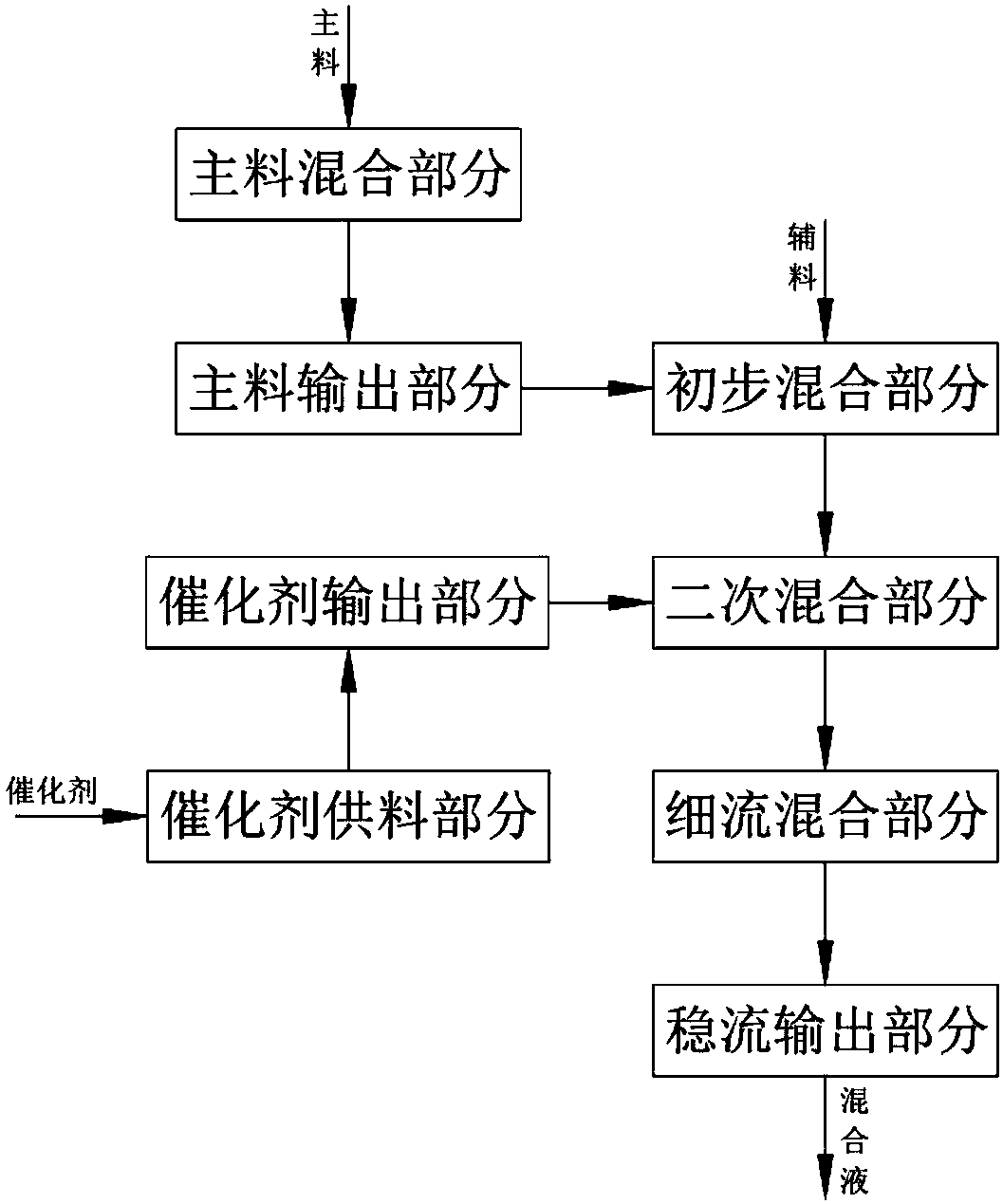
[0038] Refer to the attached figure 1 A high-efficiency production process of furan resin in Example 1 of the present invention is described.
[0039] A kind of high-efficiency production technique of furan resin, comprises the following steps:
[0040] (a) the main material output part, the main material is transmitted through the mixing part 311 on the main material output assembly 31 in a rotating manner, and at the same time, it is sprayed out through the jet outlet 3113 through the main material bin under the action of rota...
Embodiment 2
[0049] Wherein, the same or corresponding parts as those in the first embodiment adopt the reference numerals corresponding to the first embodiment. For the sake of simplicity, only the differences from the first embodiment are described below; the difference between the second embodiment and the first embodiment is that : the jet hole 3113 is set in a spiral structure, the main material is sprayed out through the jet hole 3113 to form a main material layer spaced up and down, and the auxiliary material after diverging and splashing through the groove 3251 is between the main material layers.
[0050] Further, the step (c) includes the catalyst output part, the spray flow assembly 41 is connected with the main bin 312 in a synchronous rotation manner, and the roller 417 arranged on the mixing chamber 1 and the top protrusion at the bottom of the spray flow assembly 41 The table 416 is driven in a guiding transmission mode to realize the upward movement of the storage part 411 i...
Embodiment 3
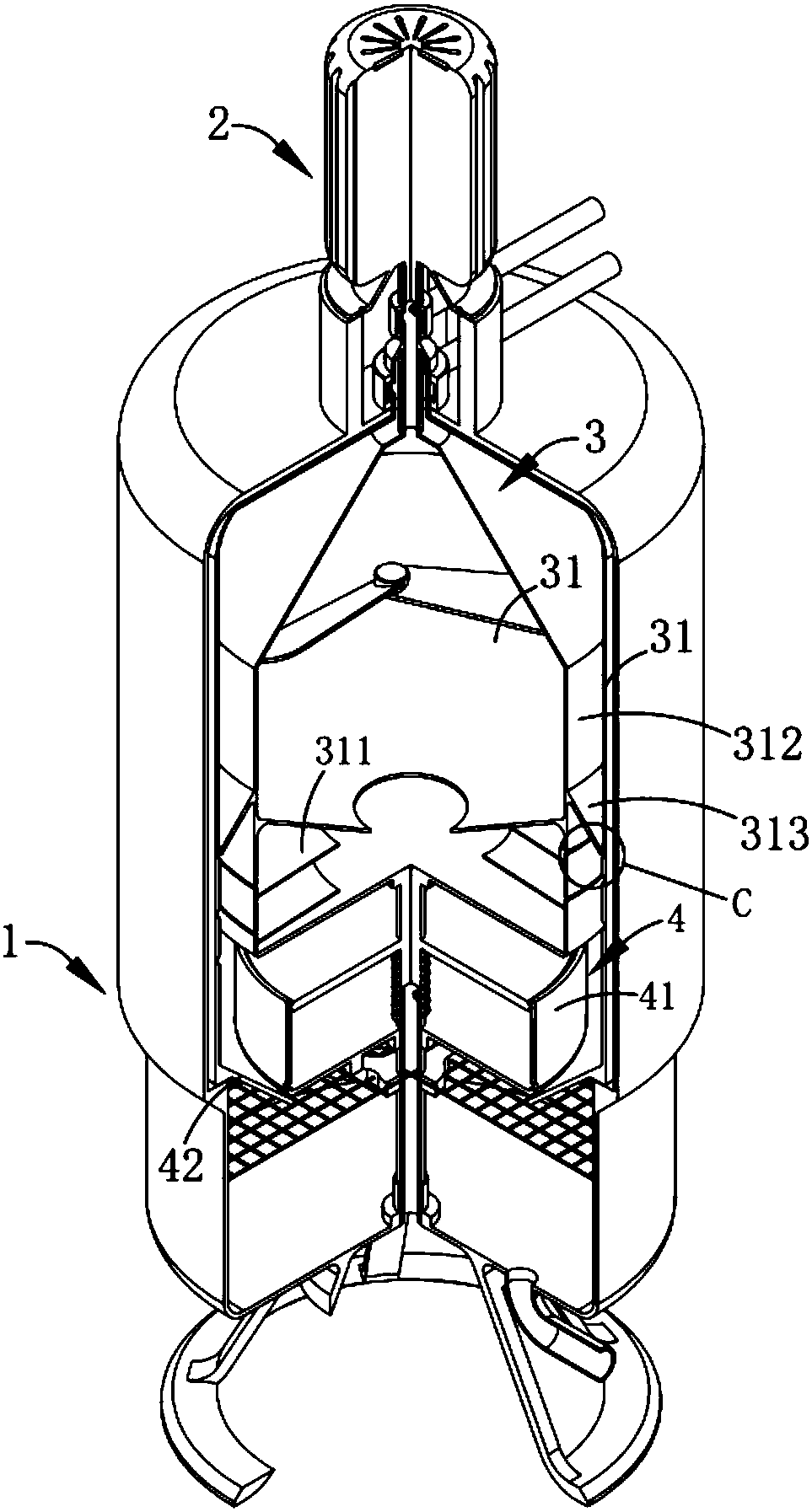
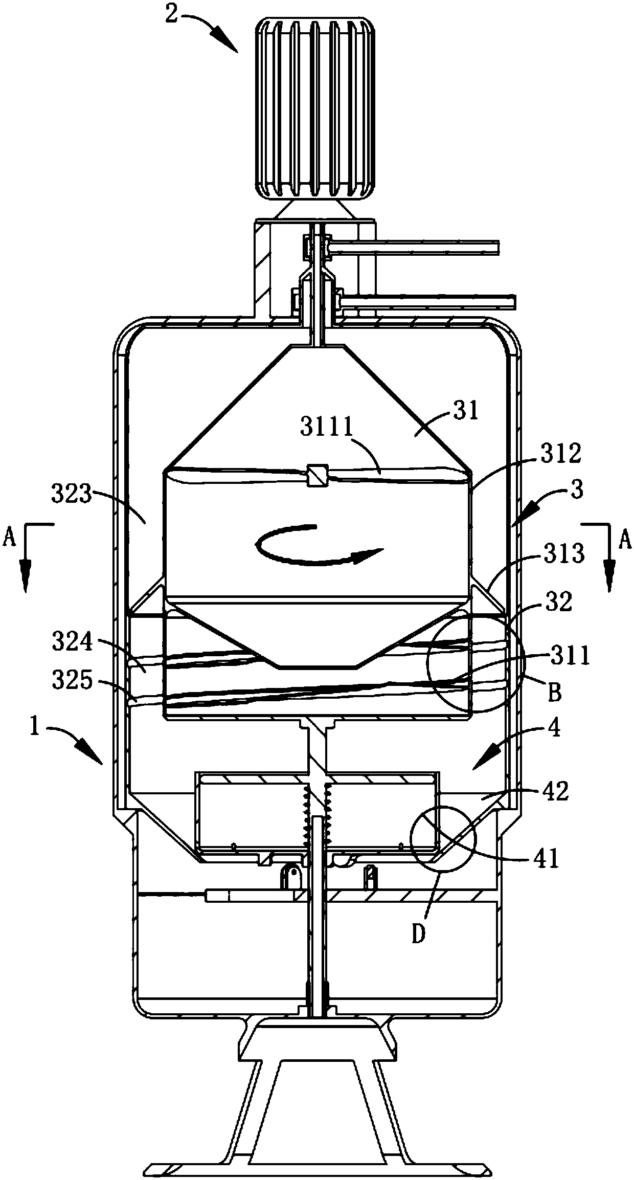
[0058] Reference attached Figure 2-10 A spiral multi-component mixing production device in Example 3 of the present invention is described.
[0059] Such as figure 2 , 3 , 4, 5, 6, 7 and 8, a spiral multi-component mixing production device includes a mixing chamber 1 and a driving mechanism 2, and also includes:
[0060] Preliminary mixing mechanism 3, described preliminary mixing mechanism 3 is arranged in the described mixing chamber 1, and it comprises main material output assembly 31 and auxiliary material mixing assembly 32, and the main material in main material output assembly 31 is mixed by being arranged on it After the output is driven by the part 311, it is ejected in a spiral structure; the auxiliary material in the auxiliary material mixing assembly 32 flows continuously through the flow port 321 arranged on it, and forms a liquid flow layer 322 below it; in this embodiment, the flow layer 322 The mouth 321 is provided with a continuous annular mouth, and the...
PUM
 Abstract
Description
Claims
Application Information
 - R&D
- Intellectual Property
- Life Sciences
- Materials
- Tech Scout
- Unparalleled Data Quality
- Higher Quality Content
- 60% Fewer Hallucinations
Browse by: Latest US Patents, China's latest patents, Technical Efficacy Thesaurus, Application Domain, Technology Topic, Popular Technical Reports.
© 2025 PatSnap. All rights reserved.Legal|Privacy policy|Modern Slavery Act Transparency Statement|Sitemap|About US| Contact US: help@patsnap.com


