
A composite magnetic field type magnetorheological polishing head

A technology of magnetorheological polishing and compound magnetic field, which is applied in the field of polishing head, can solve the problems that it is difficult to accurately adjust the magnetic field strength in the polishing area, the electromagnet is easy to affect the polishing effect, and the electromagnet occupies a large space, so as to make up for the poor controllability of the magnetic field , Reduce the heat generation, the effect of less coil turns

Active Publication Date: 2019-04-05
NORTHEASTERN UNIV LIAONING
View PDF7 Cites 0 Cited by
  • Summary
  • Abstract
  • Description
  • Claims
  • Application Information

AI Technical Summary

Problems solved by technology

[0003] The electromagnetic magneto-rheological polishing head disclosed in Chinese patent (publication number CN 1486821A) uses an electromagnet as the excitation device for magnetorheological polishing. The magnetic field strength in the polishing area can be changed by changing the excitation current. The control is simple and convenient, but the electromagnetic Iron takes up a lot of space, and with the increase of polishing time, the electromagnet heats up seriously and easily affects the polishing effect, so a special cooling mechanism needs to be designed
Chinese patent (publication number CN 106736879A) discloses a roller-type magnetorheological polishing device and method, which uses permanent magnets as the excitation device for magnetorheological polishing and is installed in the polishing shaft. The permanent magnets occupy a small space and will not There is a heating problem, but it is difficult to accurately adjust the magnetic field strength in the polishing area. The magnetic field strength in the polishing area can only be adjusted indirectly by adjusting the distance between the permanent magnet and the inner wall of the polishing shaft or the distance between the outer wall of the polishing shaft and the polished surface of the workpiece. The controllability is poor.

Method used


Image

  • A composite magnetic field type magnetorheological polishing head
  • A composite magnetic field type magnetorheological polishing head
  • A composite magnetic field type magnetorheological polishing head

Examples


Embodiment Construction

[0021] Below, the present invention will be described in further detail in conjunction with the accompanying drawings.

[0022] Such as figure 1 As shown, the composite magnetic field type magnetorheological polishing head of the present invention mainly includes:

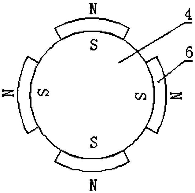
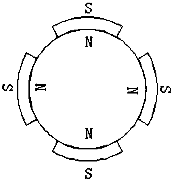
[0023] Transmission shaft 1, workpiece 2, polishing head 3, left iron core 4, excitation coil 5, NdFeB magnetic tile 6, left magnetic isolation plate 7, magnetorheological fluid 8, right magnetic isolation plate 9, right iron core 10, Infusion tube 11, concrete structure is as follows:

[0024] The polishing head 3 is installed at the center of the inner wall of the workpiece 2. The gap between the polishing head 3 and the inner wall of the workpiece 2 is 1mm. Movement, the workpiece 2 makes a reciprocating linear motion relative to the polishing head 3, the left iron core 4 and the right iron core 10 are respectively installed on the left and right sides of the polishing head 3, and the two ends of the left iron...


PUM


Abstract

The invention discloses a composite magnetic field type magnetorheological polishing head, which includes a transmission shaft, a workpiece, a polishing head, a left iron core, an excitation coil, a NdFeB magnetic tile, a left magnetic isolation plate, a magnetorheological fluid, and a right magnetic isolation plate. plate, right iron core, infusion tube, and the polishing head is installed at the center of the inner wall of the workpiece. Both ends of the polishing head are threadedly connected to the transmission shaft and the infusion pipe respectively. The polishing head is driven by the transmission shaft to rotate at a high speed relative to the inner wall of the workpiece, and the workpiece is relatively polished. The head makes reciprocating linear motion. The structure of the invention is simple. The electromagnet and the permanent magnet are combined as an excitation device for magnetorheological polishing. When a sufficient magnetic field intensity is provided, the excitation device occupies a small space and generates less heat, which can be achieved. Accurate adjustment of the magnetic field intensity in the polishing area, especially suitable for polishing the inner wall of slender non-magnetic pipe fittings.

Description

technical field [0001] The invention designs a polishing head, and in particular relates to a composite magnetic field type magnetorheological polishing head for processing the inner wall of a slender non-magnetic pipe. Background technique [0002] Magneto-rheological polishing is an emerging ultra-precision machining technology. It uses the rheological properties of magnetorheological fluid under the action of a magnetic field to polish the surface of the workpiece. It has the advantages of good controllability, stable material removal and good polishing effect. Under the action of the gradient magnetic field, the apparent viscosity and shear yield stress of the magnetorheological fluid increase rapidly, forming a flexible polishing mold that matches the surface to be processed. Shear to remove. The hardness of the polishing die can be controlled according to the strength of the magnetic field. In a certain range, the yield stress of the magnetorheological fluid increases...

Claims


Application Information

Patent Timeline
Patent Type & Authority Patents(China)
IPC IPC(8): B24B1/00B24B41/04
CPCB24B1/005B24B41/04
Inventor 宋万里石沛修世超王娜
Owner NORTHEASTERN UNIV LIAONING
Learn More