
A digitally controlled active igbt drive circuit

A driving circuit and circuit technology, which is applied in the direction of electrical components, electronic switches, pulse technology, etc., can solve the problems of high power loss, junction temperature rise, and active clamping technology that cannot meet the needs of use, so as to ensure stable operation and suppress Effect of shutting down voltage spikes and avoiding catastrophic consequences

Active Publication Date: 2021-02-12
HANGZHOU FIRSTACK TECH
View PDF9 Cites 0 Cited by
  • Summary
  • Abstract
  • Description
  • Claims
  • Application Information

AI Technical Summary

Problems solved by technology

[0003] At present, the active clamping technology in the commonly used IGBT driving equipment cannot meet the needs of use, and there are the following shortcomings in application:
[0004] 1. During the turn-off process of the IGBT, a voltage spike will be generated due to busbar noise, bus voltage fluctuations, and too much turn-off current. The overvoltage breakdown caused by the induced voltage spike during the IGBT turn-off transient will cause Larger power loss, the generated Joule heat promotes the cumulative rise of the junction temperature until irreversible damage occurs;
[0005] 2. The IGBT control circuit generally adopts analog circuit technology, and the control is not precise enough in the driving process;

Method used


Image

  • A digitally controlled active igbt drive circuit

Examples


Embodiment Construction

[0024] The present invention will be further described below in conjunction with the accompanying drawings.

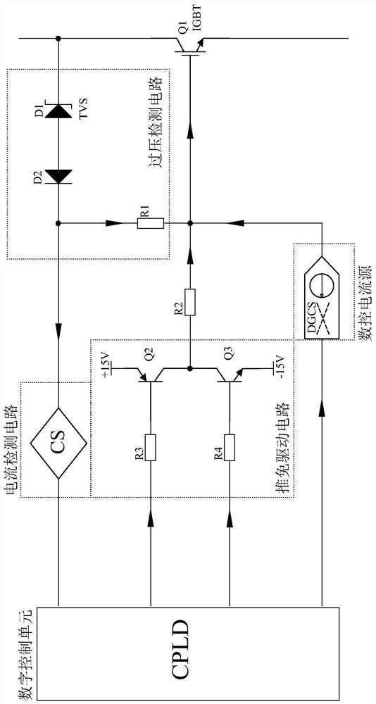
[0025] Such as figure 1 The digitally controlled active IGBT drive circuit shown includes a digital control unit, a push-pull drive circuit, an overvoltage detection circuit, a current detection circuit, a digitally controlled current source and an IGBT. The digital control unit is used to receive and calculate the signal sent by the current detection circuit, and send the control signal to the numerical control current source in combination with the PWM signal sent by the digital control unit to the push-pull circuit; the push-pull drive circuit is used to send the signal sent by the digital control unit The PWM signal is converted into an available drive signal for the IGBT; the overvoltage detection circuit is connected between the current detection circuit and the collector of the IGBT, the signal output end of the push-pull drive circuit is connected to the gate o...


PUM


Abstract

The invention discloses a digitally controlled active IGBT drive circuit, which relates to the field of semiconductor device drive circuits, including a digital control unit, a push-pull drive circuit, an overvoltage detection circuit, a current detection circuit, a digitally controlled current source and an IGBT; It is used to receive and calculate the signal sent by the current detection circuit, and combine the PWM signal sent by the digital control unit to the push-pull circuit to send a control signal to the numerical control current source; the push-pull drive circuit is used to convert the PWM signal sent by the digital control unit into an IGBT Available drive signals; the overvoltage detection circuit is connected between the current detection circuit and the collector of the IGBT, the signal output end of the push-pull drive circuit is connected to the gate of the IGBT, and the digital current source is connected to the overvoltage detection circuit. The invention improves the accuracy of the IGBT drive control circuit and effectively suppresses the IGBT turn-off voltage peak.

Description

technical field [0001] The invention relates to the field of driving circuits for semiconductor devices, in particular to a digitally controlled active IGBT driving circuit. Background technique [0002] IGBT (Insulated Gate Bipolar Transistor or Insulated Gate Bipolar Transistor) has the advantages of small driving power, low saturation voltage, and fast switching speed. Power supply, lighting circuit, traction drive, wind power generation, photovoltaic power generation, new energy vehicles and other fields. [0003] At present, the active clamping technology in the commonly used IGBT driving equipment cannot meet the needs of use, and there are the following shortcomings in application: [0004] 1. During the turn-off process of the IGBT, a voltage spike will be generated due to busbar noise, bus voltage fluctuations, and too much turn-off current. The overvoltage breakdown caused by the induced voltage spike during the IGBT turn-off transient will cause Larger power los...

Claims


Application Information

Patent Timeline
Patent Type & Authority Patents(China)
IPC IPC(8): H03K17/567H03K17/082
CPCH03K17/0828H03K17/567H03K2217/0027
Inventor 施贻蒙徐晓彬李军王文广丁文建杨昌国张杰
Owner HANGZHOU FIRSTACK TECH
Learn More