
Support, electronic device, and method for manufacturing the same

一种电子设备、制造方法的技术,应用在电气设备外壳/柜子/抽屉、电气元件、电数字数据处理等方向,能够解决橡胶垫脚剥落、橡胶垫脚与框架底面粘接减弱、橡胶垫脚作业繁杂等问题,达到易于安装、不易脱落的效果

Inactive Publication Date: 2018-03-20
LENOVO (SINGAPORE) PTE LTD
View PDF8 Cites 1 Cited by
  • Summary
  • Abstract
  • Description
  • Claims
  • Application Information

AI Technical Summary

Problems solved by technology

As a result, over time, the bond between the rubber feet and the underside of the frame may weaken, causing the rubber feet to peel off
In addition, the work of attaching the rubber feet to the bottom of the frame becomes complicated

Method used


Image

  • Support, electronic device, and method for manufacturing the same
  • Support, electronic device, and method for manufacturing the same
  • Support, electronic device, and method for manufacturing the same

Examples


no. 1 approach

[0027] Such as figure 1 As shown, the notebook computer 1 has a main body 2 and a cover body 3 , wherein the cover body 3 is hinged to the rear end of the main body 2 and can be opened and closed relative to the main body 2 . On the surface of the cover body 3 facing the main body 2, for example, a liquid crystal display 4 displaying various information is provided.

[0028] The main body 2 has a flat box-like frame 5 . The frame 5 is constituted by attaching the upper surface cover 6 and the bottom surface cover 7 to face each other. A substrate, CPU, memory, HDD, SDD, battery, and the like (hereinafter, also referred to as “internal components such as a substrate”) are accommodated inside the frame 5 . Input mechanisms such as a keyboard 8 and a touch panel 9 are provided on the upper cover 6 side of the frame 5 .

[0029] Such as figure 2 As shown, supports 100 , 102 , 104 , and 106 (hereinafter collectively referred to as “supports 10 ”) are respectively attached to t...

no. 2 approach

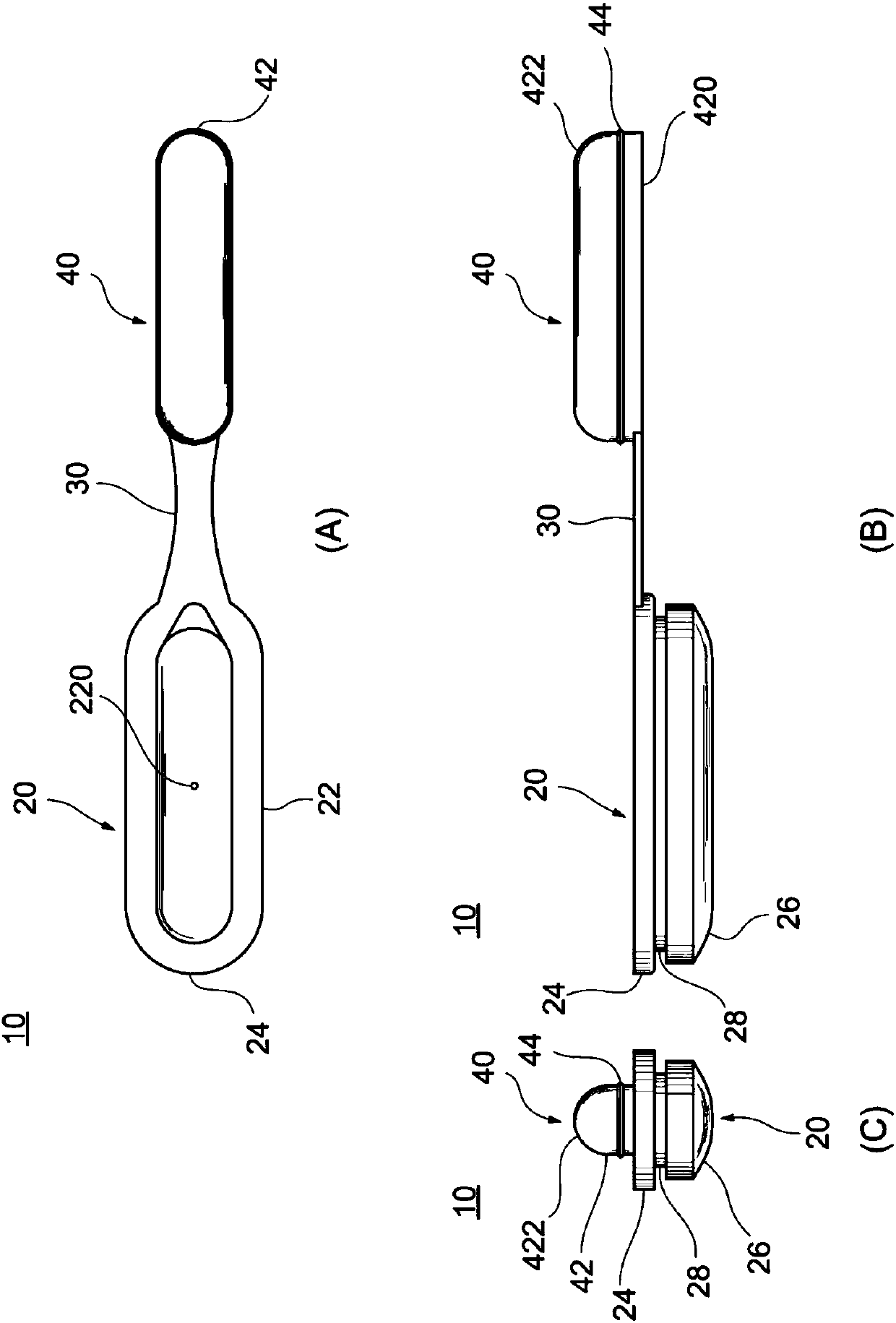
[0057] Next, use Figure 7 and Figure 8 10 A of support bodies concerning 2nd Embodiment of this invention are demonstrated. The support body 10A differs from the support body 10 of the first embodiment in that the concave portion of the first member and the convex portion of the second member have different shapes. The rest of the structure of the support body 10A is substantially the same as the structure of the support body 10 , and hereinafter, the same reference numerals and names are assigned and descriptions thereof are omitted.

[0058] Such as Figure 7 As shown, the shape of the second member 40A of the support body 10A is different from that of the concave portion 22 of the first member 20, and the upper surface 422A of the convex portion 42A is in a shape that is concave toward the inner side of the center except for both ends in the longitudinal direction (as opposed to this, in the In the support body 10 of the first embodiment, as image 3 As shown, the upp...


PUM


Abstract

The invention provides a support, an electronic device, and a method for manufacturing the same. The support can be easily installed in the frame of an electronic device and is difficult to fall. Thesupport can be easily attached to and is less likely to separate from an opening of a chassis of an electronic device. The support has a first elastic member having a recessed portion and configured to be fitted into the opening so that an opening surface of the recessed portion is directed to an inside of the chassis, and a second member having a protruding portion configured to be fitted into the recessed portion of the first member.

Description

technical field [0001] The present invention relates to a support body, an electronic device and a manufacturing method thereof. Background technique [0002] In general, supports such as rubber feet are attached to the bottom of the frame of electronic equipment such as notebook computers for the purpose of preventing sliding and shaking of the electronic equipment and absorbing impacts (for example, Patent Document 1). [0003] Patent Document 1: Japanese Patent Laid-Open No. 2003-167644 [0004] However, the installation of such rubber feet towards the surface of the frame is carried out by means of double-sided tape, adhesive. Alternatively, it is attached to a hole or the like on the bottom surface of the frame by thermally fusing a part of the rubber feet or the like. As a result, over time, the bond between the rubber feet and the underside of the frame may weaken, causing the rubber feet to peel off. In addition, the work of attaching the rubber feet to the bottom...

Claims


Application Information

Patent Timeline
Patent Type & Authority Applications(China)
IPC IPC(8): G06F1/16
CPCG06F1/166G06F1/1616H05K5/0204H05K5/023H05K5/0234
Inventor 内山义治堀内茂浩森茂树大谷哲也县广明
Owner LENOVO (SINGAPORE) PTE LTD
Learn More