Wheel bearing and semi-floating type wheel bearing device having the same

A wheel and bearing technology, applied to the rigid brackets, axles, wheels and other directions of bearing components, can solve the limitations of lightweight and miniaturization, troublesome assembly, and a large number of parts, etc., to achieve lightweight and miniaturization, Easy assembly and high rigidity effect

Inactive Publication Date: 2009-03-18
NTN CORP
View PDF8 Cites 0 Cited by
  • Summary
  • Abstract
  • Description
  • Claims
  • Application Information

AI Technical Summary

Problems solved by technology

[0006] However, in such an existing wheel bearing device, multiple rows of tapered rolling bearings 53 are installed between the hub ring 54 and the half shaft sleeve 51, and the drive shaft 52 is inserted through the half shaft sleeve 51, and the hub bolt 55 The flange 56 and the hub ring 54 connecting the drive shaft 52 have such a structure that not only has limitations in reducing the weight and miniaturization of the device, but also has a large number of parts and cumbersome assembly.

Method used


Image

  • Wheel bearing and semi-floating type wheel bearing device having the same
  • Wheel bearing and semi-floating type wheel bearing device having the same
  • Wheel bearing and semi-floating type wheel bearing device having the same

Examples


Embodiment 1

[0064] Hereinafter, embodiments of the present invention will be described in detail based on the drawings.

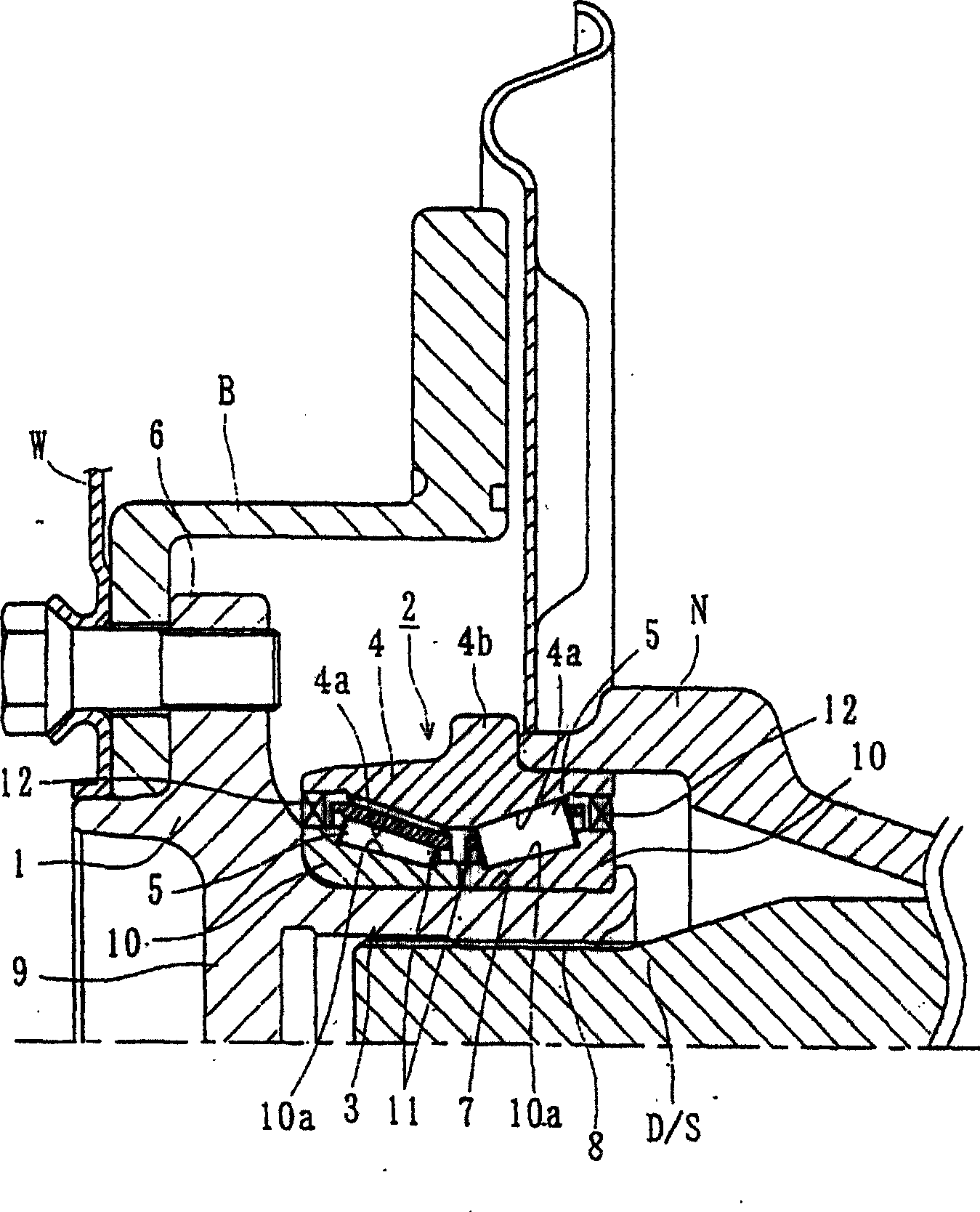
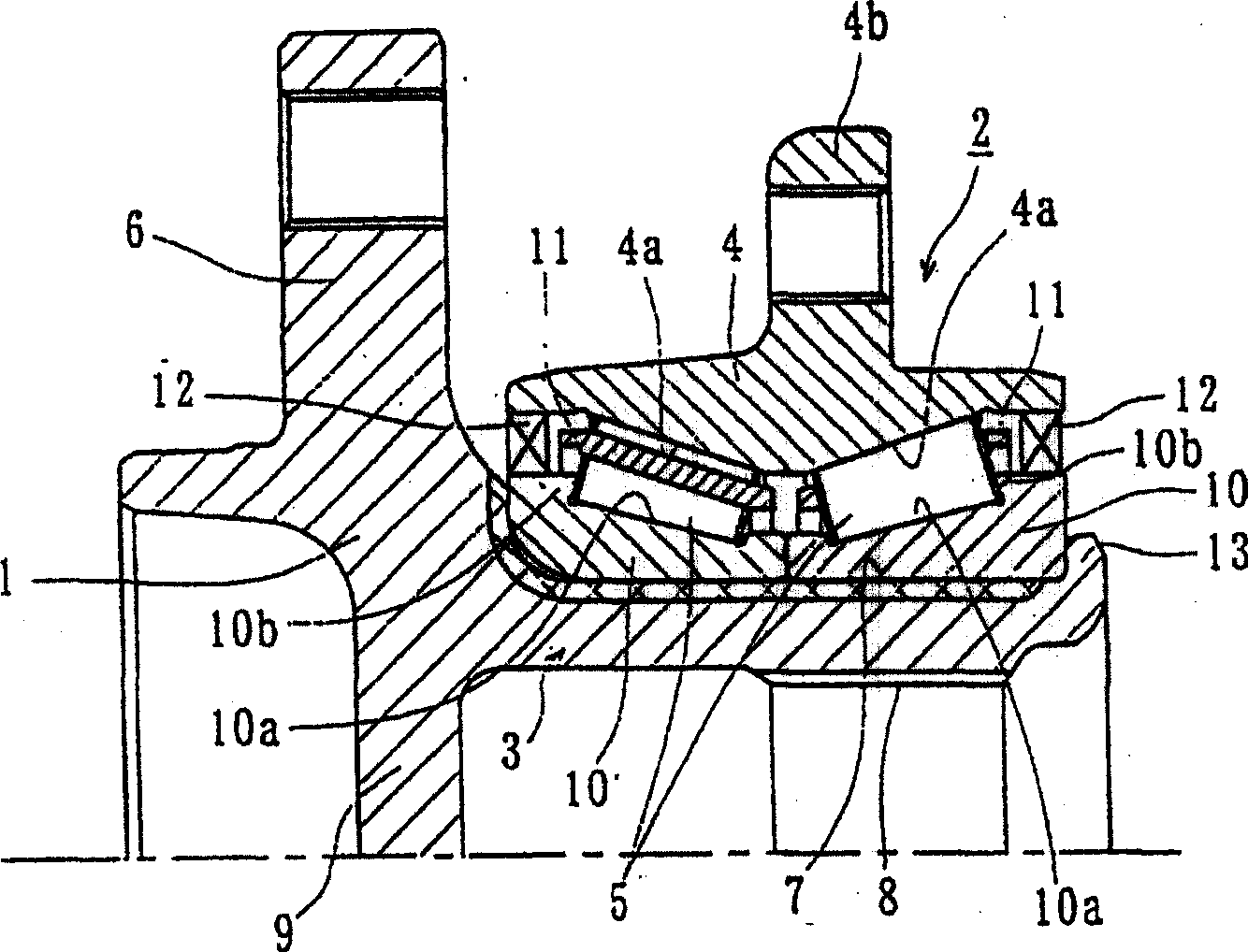
[0065] figure 1 Is a longitudinal sectional view showing the first embodiment of the wheel bearing device of the present invention, figure 2 It is a longitudinal cross-sectional view showing the bearing for the wheel. In addition, in the following description, when mounted on a vehicle, the side closer to the outside of the vehicle is called the outer side (left side of the drawing), and the side closer to the center is called the inner side of the vehicle (right side of the drawing) .

[0066] This wheel bearing device is composed of a hub ring 1 and a multi-row rolling bearing 2 as a unit, and is connected to a drive shaft D / S. The multi-row rolling bearing 2 includes an inner member 3, an outer member 4, and multiple rows of rolling elements (tapered rollers) 5, 5 housed between the two members 3, 4 to roll freely. Here, the inner member 3 refers to the hub ring 1 an...

Embodiment 2

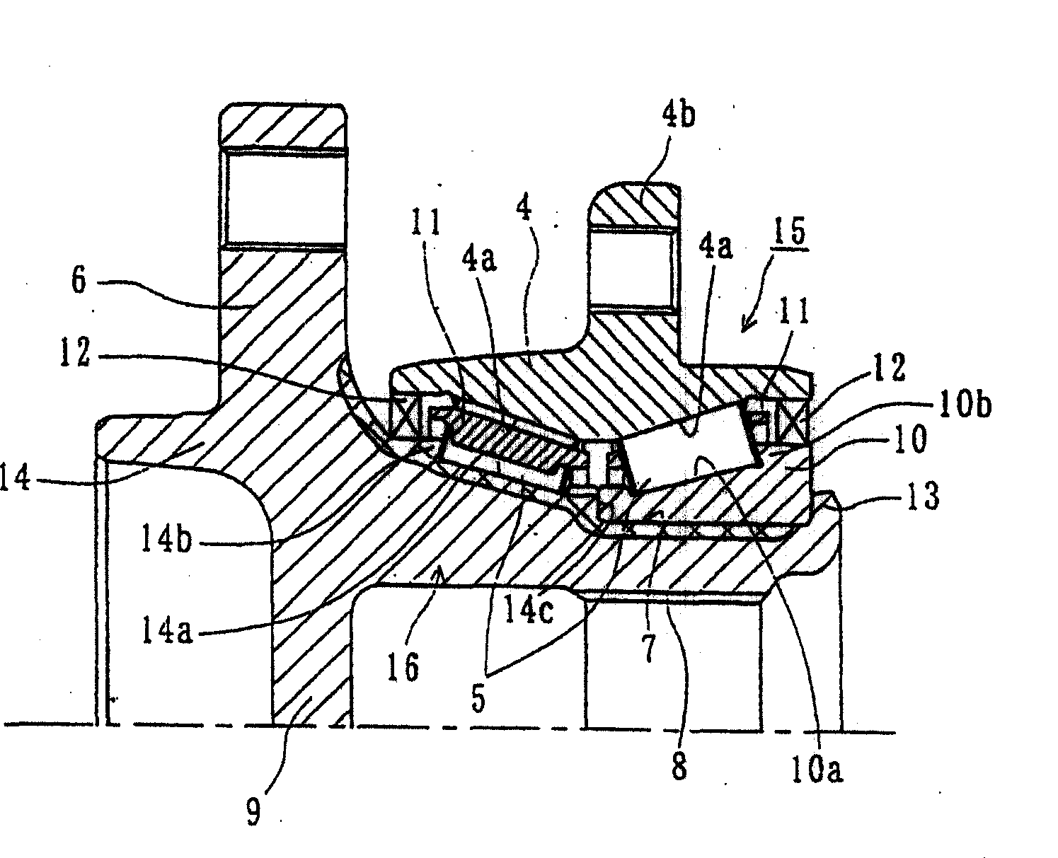
[0073] image 3 It is a longitudinal cross-sectional view showing the second embodiment of the wheel bearing device of the present invention. In this embodiment, only the structure of the hub wheel is different from the above-mentioned embodiment. Therefore, the same components and parts as in the above-mentioned first embodiment are given the same reference numerals, and detailed descriptions thereof are omitted.

[0074] This wheel bearing is formed by unitizing the hub ring 14 and the multi-row rolling bearing 15. The multi-row rolling bearing 15 has an inner member 16, an outer member 4, and a plurality of rows of rolling elements 5, 5 housed between the two members 16, 4 to roll freely. Here, the inner member 16 refers to the hub ring 14 and the inner ring 10 pressed into the hub ring 14. The hub ring 14 has a wheel mounting flange 6 integrated therewith. The wheel mounting flange 6 is used to mount a wheel (not shown) on the outer peripheral end of the vehicle. The hub ring ...


PUM


Abstract

Provided is a wheel bearing device reduced in weight and compacted in size and capable of preventing entry of rain, dust, or the like and leakage of differential oil. A wheel bearing device comprises an inner member (3) consisting of a cylindrical small-diameter step (7) integrally having a wheel attachment flange (6) at one end and disposed around the outer periphery to extend axially, a hub wheel (1) having serrations (8) formed around the inner periphery for engagement with a driving shaft (D / S), and a pair of inner rings (10) press-fitted on the small-diameter step (7) and having inner rolling surfaces (10a) formed around the outer periphery, an outer member (4) which has a car body attachment flange (4b) fixed to an axle tube (N) and which is formed with two rows of outer rolling surfaces (4a) around the inner periphery to be opposed to the inner rolling surfaces (10a), plural rolling elements (5) received between the two rolling surfaces for the outer and inner members (4, 3), a cage (11) rollably holding the rolling elements (5), and seals (12) for sealing the annular spaces of the inner and outer members (3, 4). The outboard end of the hub wheel (1) is integrally formed with a partition wall (9) blocking the inner diameter section.

Description

Technical field [0001] The present invention relates to a bearing device for a wheel that supports a wheel of an automobile or the like so as to be rotatable relative to a suspension device, and more particularly to a bearing device for a wheel that supports a driving wheel with a multi-row rolling bearing and a bearing device for a semi-floating wheel having the same . Background technique [0002] In automobiles with a frame structure, such as a truck, a full-floating structure is often used as the axle structure of the driving wheels. In addition, in recent drive wheel support structures, with the goal of improving assemblability, weight reduction, and miniaturization, a structure in which multiple rows of rolling bearings are unitized is often adopted. As an example of this existing structure, it has been known as Figure 4 Bearing device for wheels shown. [0003] In this wheel bearing device, a drive shaft 52 connected to a differential (not shown) is inserted into a half s...

Claims


Application Information

Patent Timeline
Patent Type & Authority Patents(China)
IPC IPC(8): B60B35/18F16C19/38F16C33/60F16C33/76F16C35/063
Inventor 大槻寿志
Owner NTN CORP
Why Eureka
Try Eureka