A support device for a diode molding machine

A support device and diode technology, applied in the direction of presses, support machines, mechanical equipment, etc., can solve problems such as vibration damage, diodes being charged by static electricity, difficulties in collecting and sorting diodes, etc., to eliminate static electricity, reduce resistance, and facilitate collection and packaging The effect of work

Active Publication Date: 2019-03-08
ANHUI MINGYANG ELECTRONICS
View PDF6 Cites 0 Cited by
  • Summary
  • Abstract
  • Description
  • Claims
  • Application Information

AI Technical Summary

Problems solved by technology

[0004] In order to overcome the above-mentioned technical problems, the purpose of the present invention is to provide a support device for a diode molding machine. The present invention securely fixes the diode molding machine through the cooperative design of the buffer mechanism and the base, and effectively protects the molding machine. It is not corroded, protects the diode from being damaged by static electricity, can form a buffer support when it is working, and solves the problem of the diode being damaged by static electricity and vibration; at the same time, through the design of the hopper, the die of the diode after compression molding Rolling down along the discharge groove in turn, can carry out neat and orderly discharge, avoiding irregular collisions between diodes, and solving the problem of difficult collection and arrangement of diodes during discharge

Method used


Image

  • A support device for a diode molding machine
  • A support device for a diode molding machine
  • A support device for a diode molding machine

Examples


Embodiment Construction

[0029] The following will clearly and completely describe the technical solutions in the embodiments of the present invention with reference to the accompanying drawings in the embodiments of the present invention. Obviously, the described embodiments are only some, not all, embodiments of the present invention. Based on the embodiments of the present invention, all other embodiments obtained by persons of ordinary skill in the art without creative efforts fall within the protection scope of the present invention.

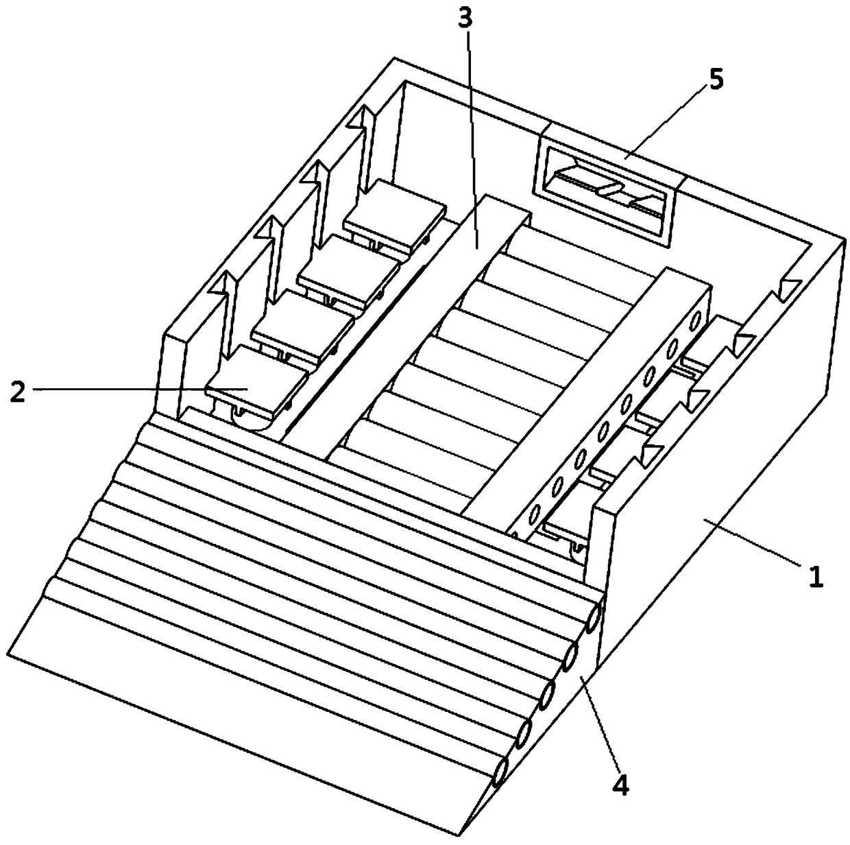
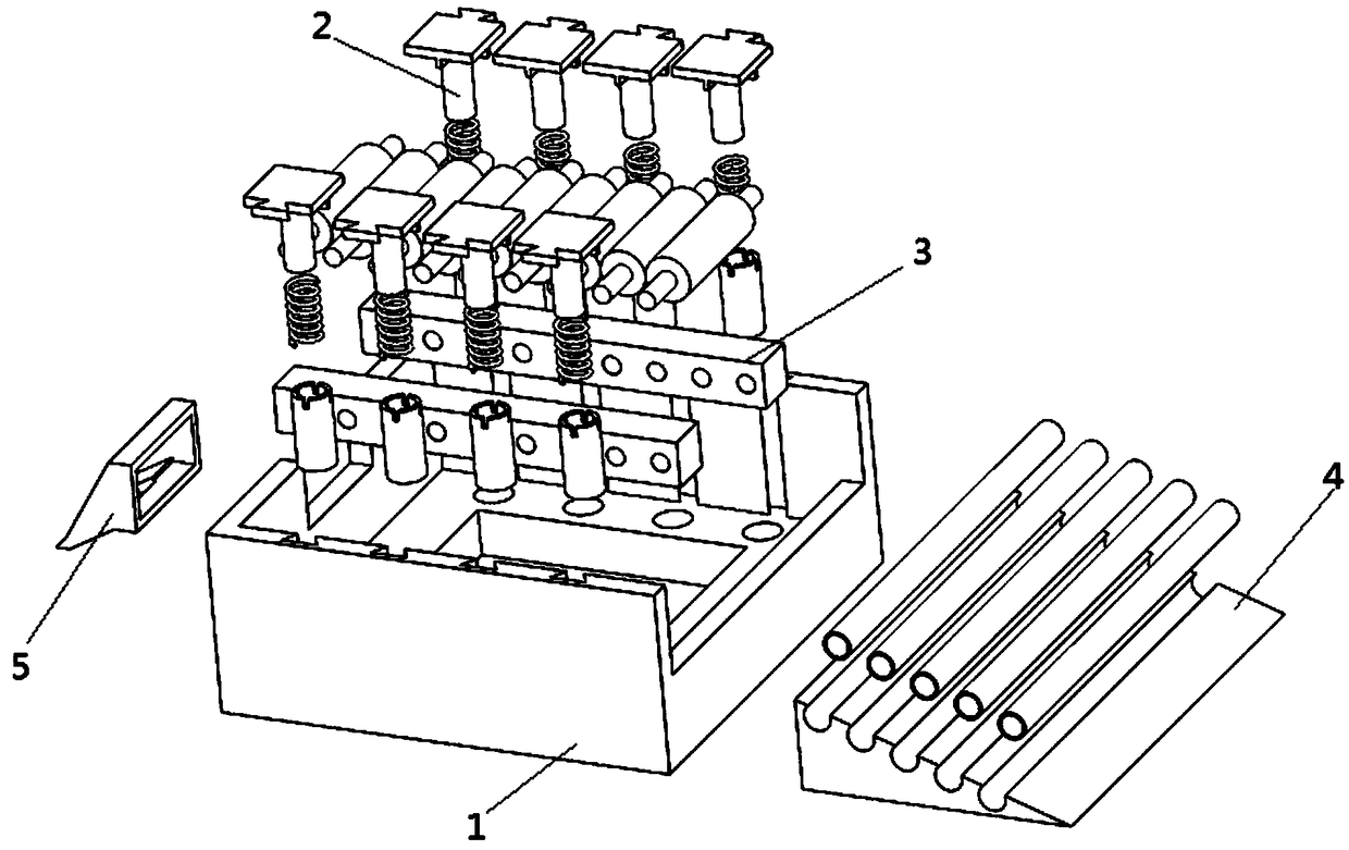
[0030] Such as figure 1 and figure 2 As shown, a support device for a diode molding machine includes a base 1, four linearly distributed buffer mechanisms 2 are installed on the left and right sides of the base 1, and two rolling support mechanisms are installed in the middle of the base 1 3. A slope platform 4 is installed on the front side of the base 1, and a discharge hopper 5 is installed on the rear side of the base 1;

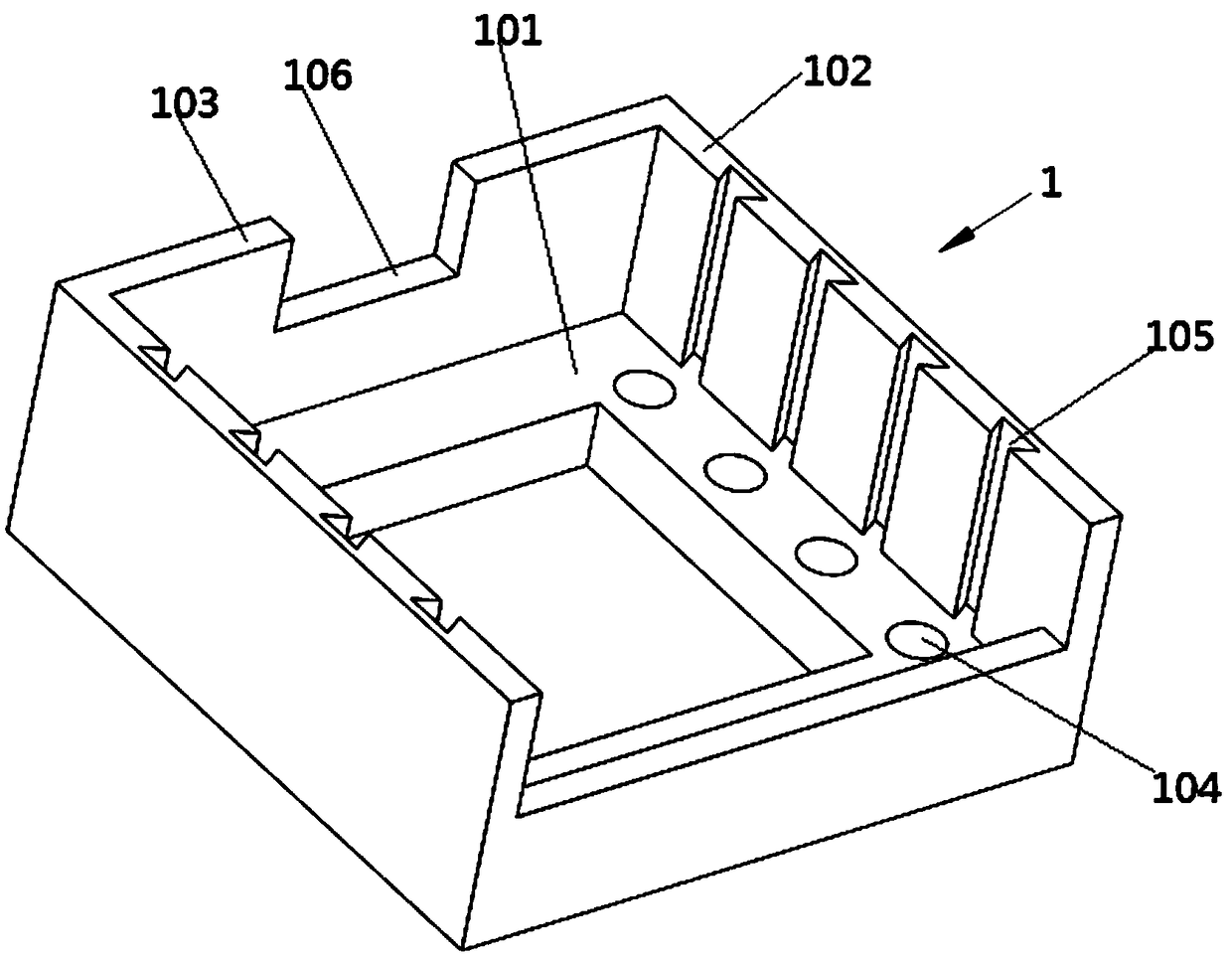
[0031] Such as image 3 As shown, ...


PUM


Abstract

The invention discloses a supporting device of a diode mould pressing forming machine. The supporting device comprises a base, four buffer mechanisms distributed linearly are installed on the left side and the right side of the base, two rolling supporting mechanisms are installed in the middle of the base, a slope platform is installed on the front side of the base, and a discharging hopper is installed on the rear side of the base. According to the supporting device, through the design of cooperation of the buffer mechanisms and the base, the diode mould pressing forming machine is firmly fixed and effectively protected against corrosion, diodes are protected against damage by static electricity, buffer supporting is formed when the forming machine works, and the problem that diodes aredamaged by static electricity and vibration is solved; and meanwhile, through the design of the discharging hopper, cores of diodes obtained after mold pressing roll down along a discharging groove, orderly and sequential discharging can be conducted, irregular collision among diodes is avoided, and the problem that diodes are difficult to collect and sort when discharged is solved.

Description

technical field [0001] The invention belongs to the field of diode manufacturing, in particular to a diode molding machine, and more specifically to a diode molding machine support device. Background technique [0002] A diode is a device with two electrodes that only allows current to flow in a single direction. The diode is mostly used for rectification, but some diodes are also used as switches and light-emitting devices. There is also a very important diode The function is to stabilize the voltage and protect the circuit, and the diode is widely used. [0003] When the diode is formed, it needs to be applied to the forming machine. At present, the forming machine on the market is only fixed on the ground by expansion screws, and then the static electricity generated during operation is exported through the ground wire. It takes a long time and is easy to be corroded. The expansion screw is connected to the ground wire. It is easy to rust, and the generated static electr...

Claims


Application Information

Patent Timeline
Patent Type & Authority Patents(China)
IPC IPC(8): B30B15/00B30B15/32F16M1/00F16M7/00F16F7/104H01L21/67
CPCB30B15/00B30B15/32F16F7/104F16M1/00F16M7/00H01L21/67011
Inventor 陈敏
Owner ANHUI MINGYANG ELECTRONICS
Why Eureka
Try Eureka