Method and system for minimal continuous-flow air-oil lubrication, with electronic regulation and control

A minimum and lubricant technology, applied in the direction of control/regulation system, non-electric variable control, ratio control, etc., can solve the problems of not being able to supply high-pressure fluid, not being able to supply, etc.

Active Publication Date: 2018-03-16
MWM微量润滑系统有限责任公司
View PDF14 Cites 4 Cited by
  • Summary
  • Abstract
  • Description
  • Claims
  • Application Information

AI Technical Summary

Problems solved by technology

[0010] Devices for the micro-supply of low-viscosity fluids are also known, such as, for example, piezoelectric micropumps, although they guarantee a minimum supply of about 1 μl / sec (microliters / second), but are not capable of supplying fluids with a certain viscosity—such as Lubricating oil - and fluids with a pressure higher than 1bar (0.9bar or 90kPa)
Therefore, these devices cannot supply high pressure fluids, as is the case with lubricant fluids that must be supplied at a pressure of at least 5 to 6 bar and immersed in compressed air lines that may also have a pressure value of 6 bar

Method used


Image

  • Method and system for minimal continuous-flow air-oil lubrication, with electronic regulation and control
  • Method and system for minimal continuous-flow air-oil lubrication, with electronic regulation and control
  • Method and system for minimal continuous-flow air-oil lubrication, with electronic regulation and control

Examples


Embodiment Construction

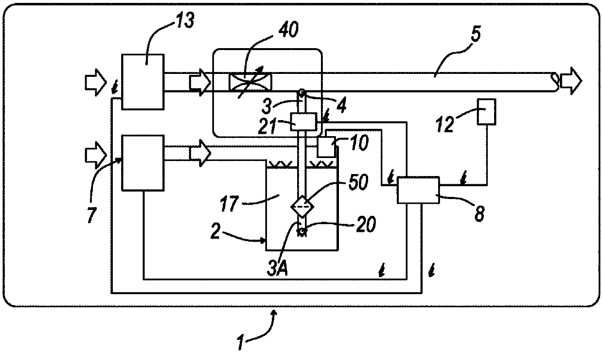
[0025] refer to figure 1 , the system according to the invention for minimal air-oil lubrication of mechanical units is indicated generally with 1 . Such a system comprises a tank 2 containing a first fluid, i.e. lubricant or oil, from which extends a first conduit 3 connected by a one-way valve 4 to the movement of a second conveying fluid in it The second pipeline 5 (for mixing). The right-angled arrangement of the ducts 3 and 5 is only intended as a non-limiting example of the invention, as these ducts may be arranged at different angles.

[0026] The tank 2 is connected to a pressure regulator 7 which generates a pressure in the tank 2 in order to obtain a predetermined flow of the first fluid or lubricant in the pipe 3 . The pressure regulator is connected to a command and control unit 8 , preferably with a microprocessor, which controls the operation of the system 1 .

[0027] This unit is also connected to a pressure sensor 10, which detects the pressure of the lubri...


PUM


Abstract

A fluid for Minimum Quantity Lubrication is obtained by mixing a lubricant with a transport fluid so as to build a biphasic mixture whereby both lubricant and transport fluid are flow and / or pressureregulated prior to mixing and whereby the lubricant is substantially continuously fed. The flow rate of the lubricant fluid is measured by sensing the back-scattering of a laser emitter on the lubricant moving with laminar motion.

Description

technical field [0001] The subject of the invention is a method of minimal lubrication of a mechanical unit in motion by means of a two-phase fluid according to the preamble of the main claim. The subject of the invention is also a system for minimal lubrication of a mechanical unit in motion by means of a two-phase fluid according to the preamble of the main claim. Background technique [0002] Systems of the above-mentioned type have been known for some time and by means of which the method as described above can be carried out. For example, DE 10 2006 030 651 describes a system for obtaining minimal lubrication of tools (with atomized oil), which comprises a system for distributing oil containing lubricant and water in a pipe moving a second delivery fluid, usually air. A nebulizer for the first fluid. The mixture thus obtained is delivered to the tool for the lubrication of its parts. Detection of the flow of lubricant fluid is also included in the system and the atom...

Claims


Application Information

Patent Timeline
Patent Type & Authority Applications(China)
IPC IPC(8): G05D11/13B23Q11/10
CPCB23Q11/1046B23Q11/1061G05D11/132Y02P70/10
Inventor 毛里齐奥·马佐尼米凯莱·诺尔贾
Owner MWM微量润滑系统有限责任公司
Why Eureka
Try Eureka