
Communication system, communication device and communication method

A technology of communication system and storage device, which is applied to the communication system between relatively movable stations, telephone communication, automatic switching office, etc., to achieve the effect of avoiding composition changes and reducing resources

Active Publication Date: 2018-03-16
HITACHI BUILDING SYST CO LTD
View PDF5 Cites 3 Cited by
  • Summary
  • Abstract
  • Description
  • Claims
  • Application Information

AI Technical Summary

Problems solved by technology

Such transformations, such as compression and decompression, require specified calculations on the data, and thus introduce specified delays in transmission

Method used


Image

  • Communication system, communication device and communication method
  • Communication system, communication device and communication method
  • Communication system, communication device and communication method

Examples


Embodiment 1

[0047] To describe the first embodiment in more detail, apply Figure 1 to Figure 18 . In order to explain the outline of the first embodiment of the present invention, the outline of each drawing is described as follows.

[0048] figure 1 The figure shows an example of constituent elements of the system configuration of the first embodiment. In order to illustrate the concept of the gist of the present invention, use figure 2 and image 3 .

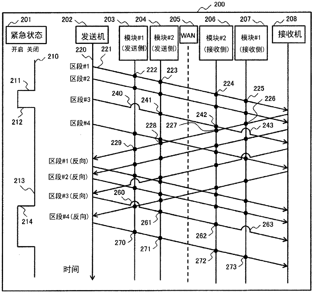
[0049] figure 2 The figure shows the application of the communication sequence and the sending and switching modules for the different segments with respect to each emergency state during the generation time of each segment.

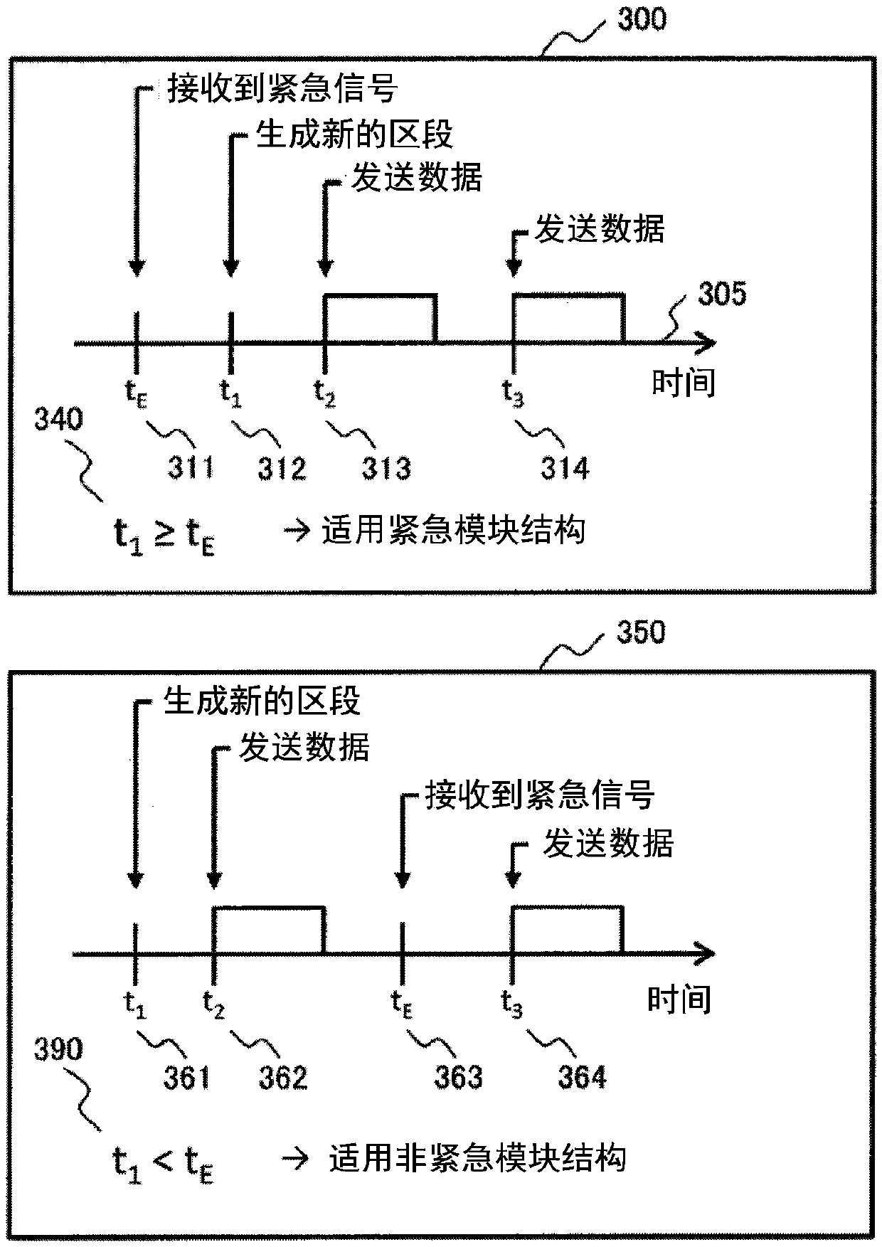
[0050] image 3 The figure shows the generation of the different segments and the instants of emergency signal reception and the comparison of the individual instants, the figure shows a simplified overview of the different module structures.

[0051] In both drawings, the method of determining whether to...


PUM


Abstract

The objective of the invention is to solve the problem that even if processed resources are few, few data can be processed in a time delayed manner, e.g., when emergent sending or non-emergent sendingwhich is performed about emergent states of an elevator is suitable for different module structures. According to the invention, data is sent to a calling center from an elevator; at least one of a first module and a second module is used for processing data; an emergent state and a non-emergent state can be set; in a starting section of the non-emergent state, for the non-emergent setting, the first module and the second module are used for processing data; in the starting section of the emergent state, for the emergent setting, the first module is not used and the second module is used forprocessing the data; then, in the section suitable for the emergent setting, even if the emergent state is converted to be non-emergent state in the middle process, the method is continuously suitablefor emergent setting until the section is finished.

Description

technical field [0001] The present invention relates to a technique for switching a data communication method according to a situation. This concerns, for example, the transmission of data relating to the emergency state of the elevator when transmitting data between the elevator control unit and the call center. Background technique [0002] In order to maintain a plurality of elevators located in a long distance, relevant data is periodically collected on the elevator side, and the data is sent to a management department such as a call center for analysis and maintenance. The data can be, for example, detection data of various sensors, data generated by the device itself, voice input by elevator users and other data. The data is collected by the control unit, which is a small processor inside each elevator, and sent to the call center via WAN (wide-area network: Wide Area Network). [0003] In most cases, wireless technologies such as LTE (Long-Term-Evolution: Long-Term ...

Claims


Application Information

Patent Timeline
IPC IPC(8): H04B3/60H04M3/51
CPCH04B3/60H04M3/5116H04M2242/04
Inventor J·多恩霍夫谷田直辉对马雄次藤嶋坚三郎
Owner HITACHI BUILDING SYST CO LTD
Learn More