Garment steamer sprayer and garment steamer
A technology of a garment ironing machine and a spray head, applied in the field of ironing machines, can solve the problems of low steam penetration, poor wrinkle removal ability, complex structure, etc., so as to ensure the wrinkle removal effect, enhance penetration, and reduce production costs. Effect
- Summary
- Abstract
- Description
- Claims
- Application Information
AI Technical Summary
Problems solved by technology
Method used
Image
Examples
Embodiment 1
[0042] The invention provides a garment steamer, which comprises a base, a water tank disposed in the base, a support frame vertically disposed on the base and provided with a resting part on the top, and a spray head of the garment steamer hung in the resting part.
[0043] Since in this embodiment, only the structure of the spray head of the garment ironing machine is improved, and the structures of the base, water tank, and support frame are the same as those of the existing garment ironing machine respectively, so it will not be repeated here. repeat.
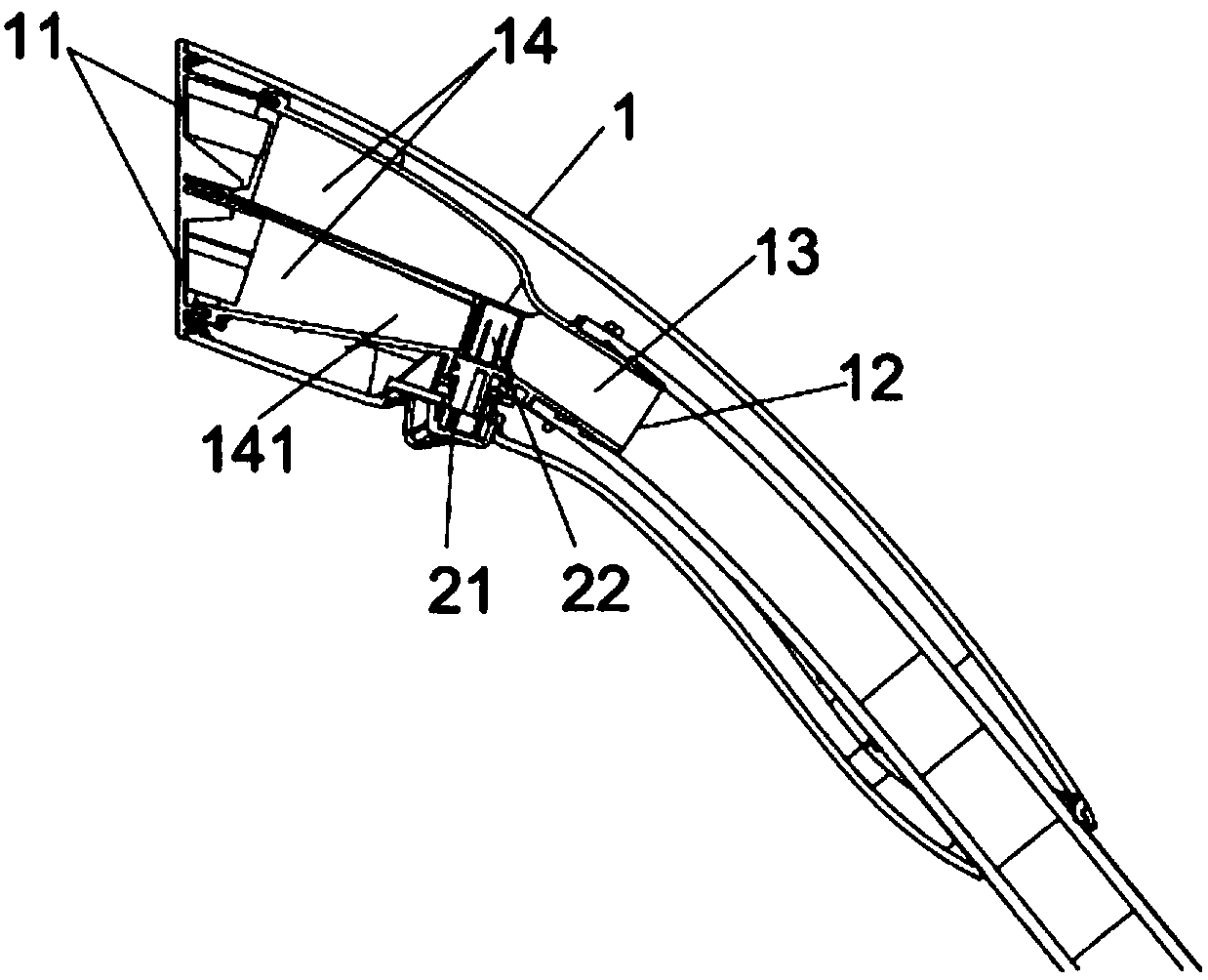
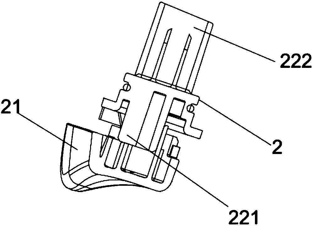
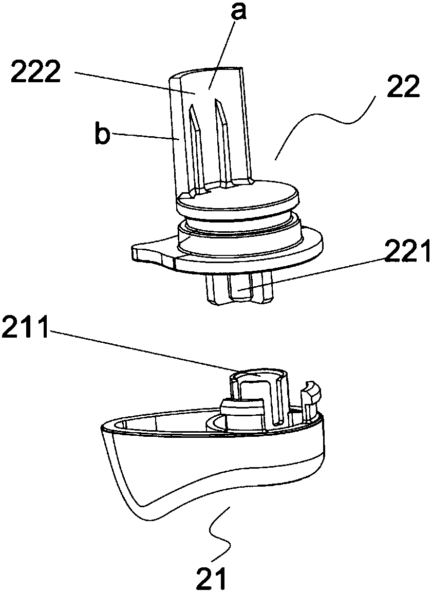
[0044] Specifically, see figure 1 , the spray head of the garment steamer includes a casing 1 . Both ends of the housing 1 are respectively provided with a steam outlet 11 and a steam inlet 12, and a steam input channel 13 is provided in it, at least two steam output channels 14 communicating with the steam input channel 13, and at least two steam output channels 14 arranged in the steam input channel There is at least on...
Embodiment 2
[0068] The structure of this embodiment is basically the same as that of Embodiment 1, the difference is that the structure of the control switch 21 and the opening and closing member 22 is changed, that is, please refer to Figure 10 , the control switch 21' is a button switch or a slide switch. The communication port B is a channel structure bent and facing the top surface of the opening and closing member. And the opening and closing member 22' includes a driving column 221' and a sealing plug 222'; one end of the driving column 221' is connected to the sealing plug 222', and a spring 223' is sheathed on the other end and connected to the control switch 21' Connection; the plugging plug 222' is facing towards the communication port B.
[0069] see Figure 11 with Figure 12 , by pressing or sliding the control switch 21' to drive the driving column 221' to compress the spring 223', the driving column 221' drives the sealing plug 222' to move to the communication port B a...
Embodiment 3
[0071] The structure of this embodiment is basically the same as that of Embodiment 1, the difference is that the structure of the control switch 21 and the opening and closing member 22 is changed, that is, please refer to Figure 13 , the control switch 21" is a slide switch, and the end of the control switch 21" connected to the opening and closing member 22" is obliquely provided with at least two recesses c and d with different heights. And the sealing opening and closing member 22" includes Blocking flap 221 " and push post 222 ". The blocking baffle 221" is arranged at the communication port, and one end of it is hinged to the partition side wall C between the two steam outlet channels through a clip spring, and the blocking baffle 221" passes through the clip spring. The function realizes the sealing of the communication port B'. The top end of the push post 222" abuts against the bottom surface of the blocking block 221", and the bottom end abuts against the control ...
PUM
 Abstract
Description
Claims
Application Information
 - R&D
- Intellectual Property
- Life Sciences
- Materials
- Tech Scout
- Unparalleled Data Quality
- Higher Quality Content
- 60% Fewer Hallucinations
Browse by: Latest US Patents, China's latest patents, Technical Efficacy Thesaurus, Application Domain, Technology Topic, Popular Technical Reports.
© 2025 PatSnap. All rights reserved.Legal|Privacy policy|Modern Slavery Act Transparency Statement|Sitemap|About US| Contact US: help@patsnap.com


