


Quick Research
Generate reliable direction feasibility study reports for your R&D in just a few steps.

Technical Q&A
Discover and master advanced knowledge NOW. Basics, ideas, possibilities, all at once.

Find Solutions
As an expert in R&D theories, this can generate solutions to your technical problems instantly.

Evaluate Feasibility
Analyze your overall solution with one click, know your potential R&D risks in advance.

Monitor Landscape
Get weekly tech updates, stay abreast of the latest tech innovations and key insights.
Photovoltaic bracket and arrangement method of purlines in photovoltaic bracket
A photovoltaic bracket and purlin technology, which is applied in the support structure of photovoltaic modules, photovoltaic power generation, photovoltaic modules, etc., can solve the problems of uneven stress on purlins, unreasonable layout, and waste of raw materials, so as to save raw materials, optimize purlin cross-section, The best effect of purlin section
- Summary
- Abstract
- Description
- Claims
- Application Information
AI Technical Summary
Problems solved by technology
Method used
Image

Examples
Embodiment 1
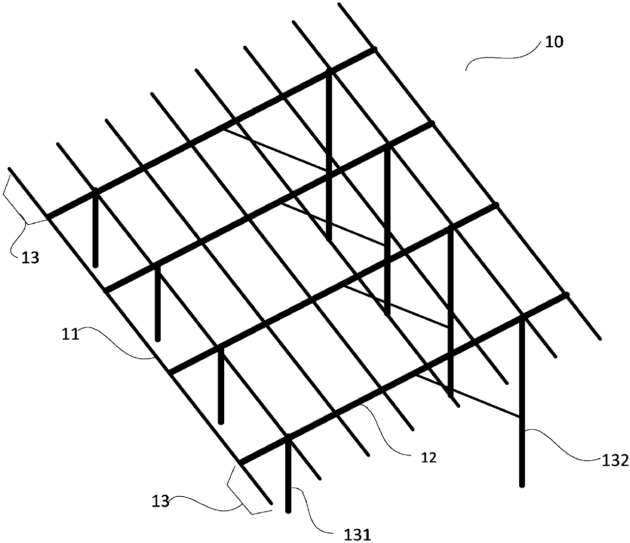
[0023] figure 1 It is a structural schematic diagram of the photovoltaic support in Embodiment 1 of the present invention. see figure 1 , a photovoltaic support 10 provided by an embodiment of the present invention includes at least two purlins 11 and at least three purlin supports 12 , and each purlin 11 has an overhang 13 . Both ends of each purlin support 12 are respectively fixed on the front column 131 and the rear column 132 , and its function is to support the purlin 11 . Wherein, the purlin 11 is fixed on the purlin support 12, and the quantity of the purlin 11 and the purlin support 12 can be set according to the actual use situation, as an example, figure 1 The number of purlins is 8, and the number of purlin supports is 4.
[0024] Specifically, there are usually multiple purlins 11 in the photovoltaic support, and the length of each purlin is the same, so the total length of each purlin can be known by calculating the total length of one of the purlins, that is,...
Embodiment 2
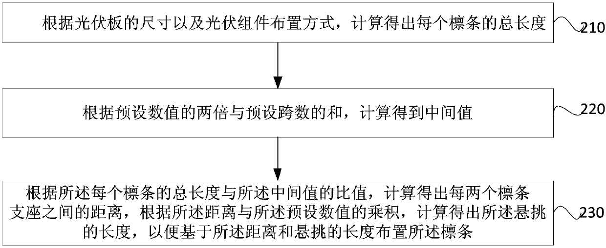
[0030] figure 2 It is a flowchart of a method for arranging purlins in a photovoltaic support provided in Embodiment 2 of the present invention. Wherein, the photovoltaic support includes at least two purlins and at least three purlin supports, and each purlin has a cantilever, such as figure 2 As shown, the method includes:
[0031] Step 210, calculate the total length of each purlin according to the size of the photovoltaic panel and the layout of the photovoltaic modules.
[0032] Step 220: Calculate and obtain an intermediate value according to the sum of twice the preset value and the preset number of strides.
[0033] Step 230, according to the ratio of the total length of each purlin to the median value, calculate the distance between every two purlin supports, and calculate according to the product of the distance and the preset value The length of the overhang so that the purlins are arranged based on the distance and the length of the overhang.
[0034] Prefera...
PUM
 Abstract
Description
Claims
Application Information
 - R&D Engineer
- R&D Manager
- IP Professional
- Industry Leading Data Capabilities
- Powerful AI technology
- Patent DNA Extraction
Browse by: Latest US Patents, China's latest patents, Technical Efficacy Thesaurus, Application Domain, Technology Topic, Popular Technical Reports.
© 2024 PatSnap. All rights reserved.Legal|Privacy policy|Modern Slavery Act Transparency Statement|Sitemap|About US| Contact US: help@patsnap.com