
Bin penetrating structure for cable sealing

A cable and cabin technology, applied in electrical components, coupling devices, circuits, etc., can solve the problems of miniaturization and light weight of the whole machine, bulky watertight connectors, high price, high reliability, flexible installation and use Convenience and simple structure

Active Publication Date: 2018-03-13
BEIJING RES INST OF PRECISE MECHATRONICS CONTROLS
View PDF3 Cites 6 Cited by
  • Summary
  • Abstract
  • Description
  • Claims
  • Application Information

AI Technical Summary

Problems solved by technology

The traditional method uses professional watertight connectors, but watertight connectors are bulky, heavy, and expensive, which is not conducive to the miniaturization and light weight of the whole machine

Method used


Image

  • Bin penetrating structure for cable sealing
  • Bin penetrating structure for cable sealing
  • Bin penetrating structure for cable sealing

Examples


Embodiment 1

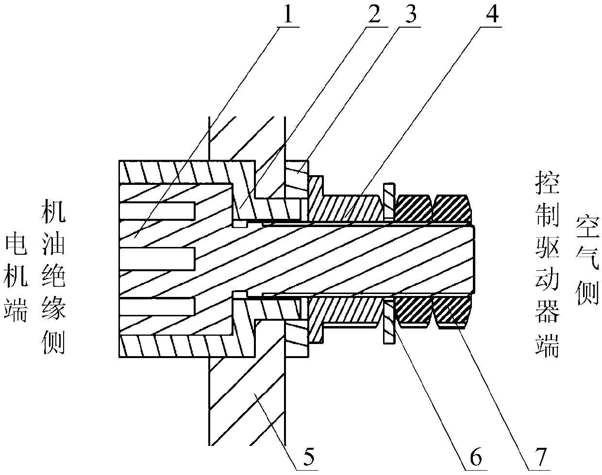
[0048] This embodiment is aimed at the transmission of power electricity between the underwater propulsion motor control driver and the motor;

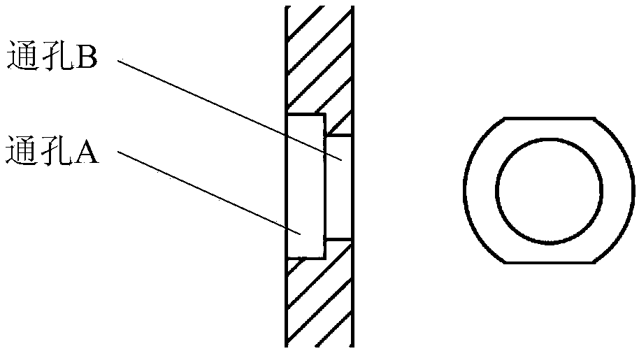
[0049] like figure 1 As shown in the figure, a cable sealing penetration structure is used for the sealing of cables between two compartments, the two compartments are respectively the motor compartment and the control drive compartment, and the two compartments are separated by a partition layer 5 for isolation; the medium in the motor compartment is oil insulating liquid, and the medium in the control drive compartment is air; the compartment 5 is a partition with stepped through holes, and the structural diagram of the compartment 5 is as follows figure 2 As shown, the stepped through hole includes a through hole A and a through hole B, the diameter of the through hole A is 26 mm, and the diameter of the through hole B is 16 mm; the top and bottom ends of the through hole A are milled flat;

[0050] The penetrating structure incl...

Embodiment 2

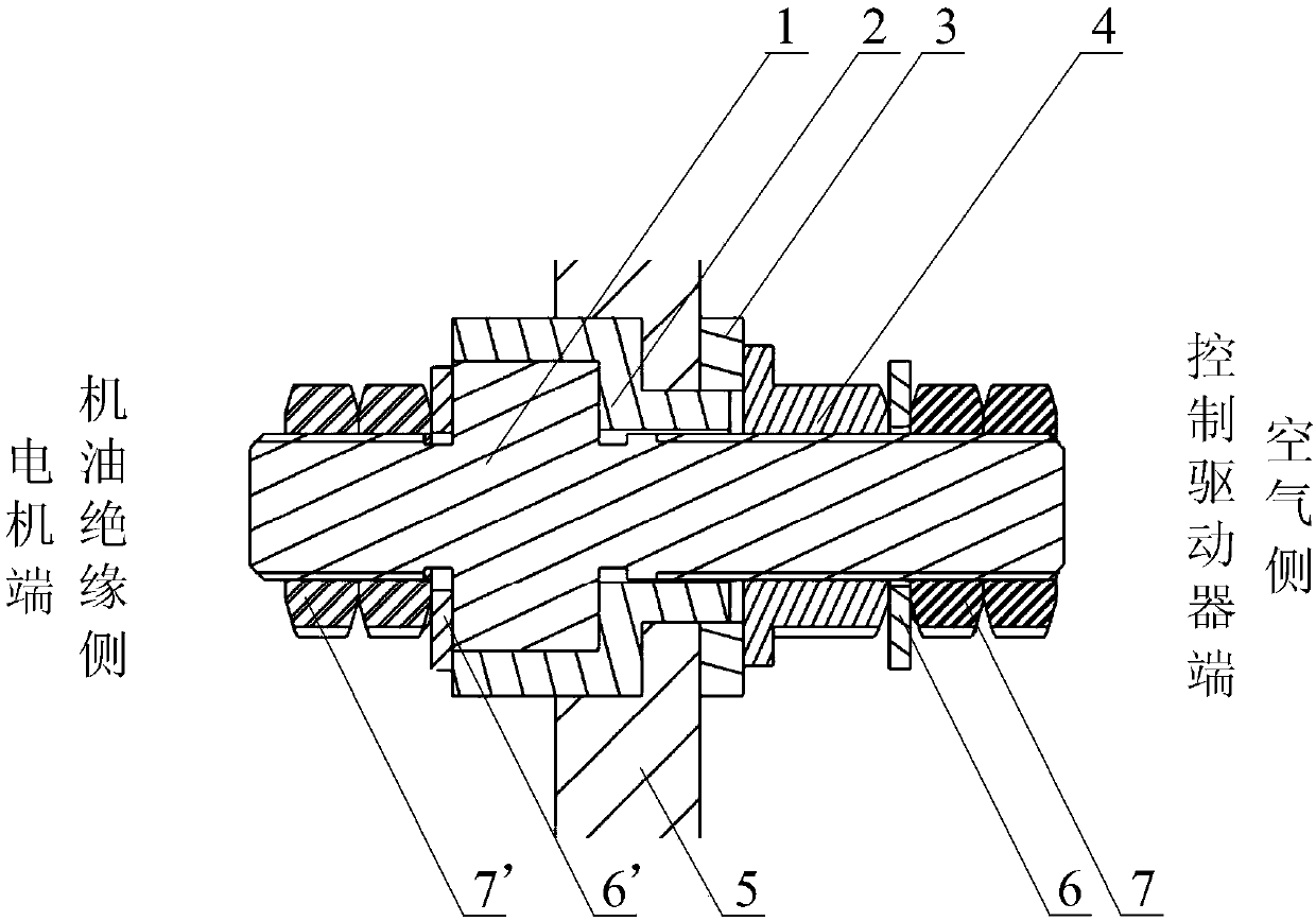
[0060] This embodiment is aimed at the transmission of power electricity between the underwater propulsion motor control driver and the motor;

[0061] like image 3 As shown in the figure, a cable sealing penetration structure is used for the sealing of cables between two compartments, the two compartments are respectively the motor compartment and the control drive compartment, and the two compartments are separated by a partition layer 5 for isolation; the medium in the motor compartment is oil insulating liquid, and the medium in the control drive compartment is air; the compartment 5 is a partition with stepped through holes, and the structural diagram of the compartment 5 is as follows figure 2 As shown, the stepped through hole includes a through hole A and a through hole B, the diameter of the through hole A is 26 mm, and the diameter of the through hole B is 16 mm; the top and bottom ends of the through hole A are milled flat;

[0062] The penetrating structure incl...


PUM

PropertyMeasurementUnit
Diameteraaaaaaaaaa
Diameteraaaaaaaaaa
Diameteraaaaaaaaaa

Abstract

The invention relates to a bin penetrating structure of cable sealing. The structure is applied into an underwater propulsion motor. When power electricity or a signal is transmitted to a control driver by a power cable or a control cable of the motor, a medium in the motor and a medium in the control driver can be isolated with each other through connecting the power cable or the control cable inthe motor with the power cable or the control cable in the control driver by the structure, namely, a cable sealing structure under the condition of bin penetrating of a cable from a liquid side to an air side is achieved. The structure is simple, is convenient to install and is reliable in sealing and low in cost, the structure is convenient and flexible to install and use, a copper core is usedfor transferring an electric signal or the power electricity, two ends can employ a welding mode, and connection also can be achieved by a wiring terminal as long as a press nut is pressed; and the structure is high in reliability, materials of an insulation sealing sleeve and an insulation sealing cushion employ polytetrafluoroethylene, insulation is ensured after pressing, and meanwhile, the pressure of 20MPa or above can be borne.

Description

technical field [0001] The invention relates to a cable sealing penetration structure, which is applied to an underwater propulsion motor. When power electricity or signals are transmitted to a control driver through a power cable or a control cable of the motor, the structure is used to protect the motor inside the motor. The power cable or control cable is transferred to the power cable or control cable in the control driver, which can realize the mutual isolation of the medium in the motor and the medium in the control driver, that is, a way to realize the cable passing from the liquid side to the air side Cable sealing structure in cabin case. Background technique [0002] In the design and application of underwater propulsion motors, the integrated design of control drives and motors has received more and more attention due to its advantages of small size, light weight, and low noise. [0003] In the integrated design process of the underwater propulsion motor, in orde...

Claims


Application Information

Patent Timeline
IPC IPC(8): H01R13/523
CPCH01R13/523
Inventor 赵曾武魏娟张军苑利维于洋
Owner BEIJING RES INST OF PRECISE MECHATRONICS CONTROLS
Learn More