Low-voltage high-power pressurized water reactor fuel assembly simulation device
A fuel assembly and simulation device technology, which is applied in the simulation process of specific applications, reactors, nuclear power generation, etc., can solve the problems of large energy consumption and complex structure of the device, and achieve the effect of reducing loss and cost and facilitating replacement
- Summary
- Abstract
- Description
- Claims
- Application Information
AI Technical Summary
Problems solved by technology
Method used
Image
Examples
Embodiment 1
[0030] like figure 1 As shown, a low-voltage high-power PWR fuel assembly simulation device includes a pressure-bearing assembly, an electric heating assembly 2, and a square flow channel, and the square flow channel is arranged in the pressure-containing assembly and is sealed with the pressure-containing assembly. The electric heating component 2 passes through the square flow channel and the pressure-bearing component simultaneously and is sealed and fixed with the pressure-bearing component. This embodiment solves the problems of electric heating, insulation and sealing by passing the electric heating assembly 2 through the square flow channel and the pressure-bearing assembly at the same time and sealing and fixing the pressure-bearing assembly, and realizes that the thermal-hydraulic characteristics are similar to those of the reactor fuel assembly. The low-voltage, high-power fuel assembly simulation process reduces the power consumption during simulation and simplifies...
Embodiment 2
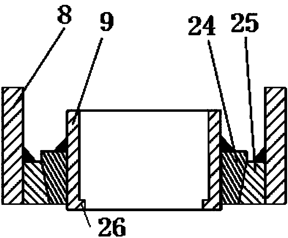
[0032] like figure 1 As shown, on the basis of Embodiment 1, the pressure-bearing assembly includes an upper flange cover 4, an upper groove flange 6, a lower groove flange 11, and a lower flange cover 17, and the upper flange cover 4 is arranged on the upper The upper groove flange 6 is fixed to each other, the lower groove flange 11 is arranged above the lower flange cover 17 and fixed to each other, the upper groove flange 6 is arranged above the lower groove flange 11, and the upper groove flange 6 and A pressure-bearing cylinder 8 is arranged between the flanges 11 on the lower groove surface, and the pressure-bearing cylinder 8 is welded and fixed to the flange 6 on the upper groove surface and the flange 11 on the lower groove surface at the same time, and the square flow channel is arranged on the pressure-bearing cylinder 8 and both ends protrude from the upper groove surface flange 6 and the lower groove surface flange 11 respectively, the electric heating component ...
Embodiment 3
[0034] like figure 1 , figure 2 As shown, on the basis of the above embodiment, the electric heating assembly 2 includes an upper conductive copper head 19, an electric heating rod bundle and a lower conductive plate 23, the top of the electric heating rod bundle passes through the upper conductive copper head 19, and the bottom of the electric heating rod bundle passes through After passing through the square runner, it is fixed with the lower conductive plate 23, and the upper conductive copper head 19 is arranged between the upper flange cover 4 and the upper groove surface flange 6 and fixed with the upper groove surface flange 6, and the upper conductive copper head 19 The top end is set in the upper flange cover 4, the bottom end of the upper conductive copper head 19 is set in the upper groove surface flange 6, and the lower conductive plate 23 is arranged in the lower groove surface flange 11. The bottom end of the upper conductive copper head 19 is recessed into an ...
PUM
 Abstract
Description
Claims
Application Information
 - R&D
- Intellectual Property
- Life Sciences
- Materials
- Tech Scout
- Unparalleled Data Quality
- Higher Quality Content
- 60% Fewer Hallucinations
Browse by: Latest US Patents, China's latest patents, Technical Efficacy Thesaurus, Application Domain, Technology Topic, Popular Technical Reports.
© 2025 PatSnap. All rights reserved.Legal|Privacy policy|Modern Slavery Act Transparency Statement|Sitemap|About US| Contact US: help@patsnap.com


