Method for synchronous shifting on an electronically controlled two-speed transfer case utilizing an electronically controlled engine and transmission
A transfer case and transmission technology, which is applied in the direction of vehicle gearbox, control device, transmission control, etc., can solve the problem of increasing the probability of the vehicle being stuck
- Summary
- Abstract
- Description
- Claims
- Application Information
AI Technical Summary
Problems solved by technology
Method used
Image
Examples
example 1
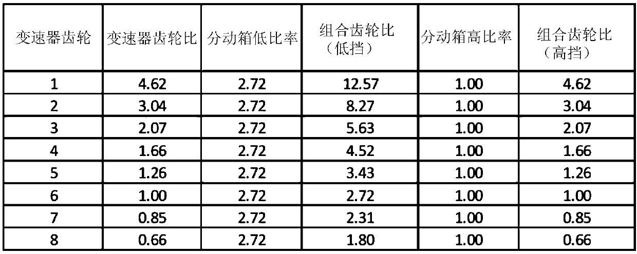
[0033] have figure 2 The vehicle with the exemplary gear ratios shown in is operated with the transmission in fourth gear and the transfer case in its low range, where the transmission input shaft speed 102 is 2500 rpm. Look image 3 or Figure 4 In column 214, the combined gear ratio of transmission input shaft speed 102 to transfer case output speed 106 is 4.52. Transfer case output speed 106 is found by dividing (transmission input shaft speed 102) by (combined gear ratio), which equals 2500 / 4.52, or 553 rpm. This can be done with the transfer case in its high range and the transmission in first gear (combined gear ratio = from image 3 or Figure 4 The same transfer case output speed 106 of 553 rpm is achieved by 4.62 of the row 216 of , where the transmission input shaft speed 102 is equal to 2555 rpm (2555 / 4.62=553). The ratio of transmission input shaft speed 102 resulting in the same transfer case output speed 106 can be calculated as 2555 / 2500, or 1.022. In oth...
example 2
[0035] have figure 2 The vehicle with the exemplary gear ratios shown in is operated with the transmission in second gear and the transfer case in its high gear, where the transmission input shaft speed 102 is 2500 rpm. Look image 3 or Figure 4 The combined gear ratio of transmission input shaft speed 102 to transfer case output speed 106 is 3.04 across row 216 . Transfer case output speed 106 is found by dividing (transmission input shaft speed 102) by (combined gear ratio), which equals 2500 / 3.04, or 822 rpm. This can be done with the transfer case in its low range and the transmission in fifth gear (combined gear ratio = from image 3 or Figure 4 3.43 of column 214 of ) achieves the same transfer case output speed 106 of 822 rpm, where the transmission input shaft speed 102 is equal to 2819 rpm (2819 / 3.43=822). The ratio of transmission input shaft speed 102 resulting in the same transfer case output speed 106 can be calculated as 2819 / 2500, or 1.12. In other word...
example 3
[0037] In this example, the same initial conditions as presented above in Example 2 will be used. have figure 2 The vehicle with the exemplary gear ratios shown in is operated with the transmission in second gear and the transfer case in its high gear, where the transmission input shaft speed 102 is 2500 rpm. Look image 3 or Figure 4 The combined gear ratio of transmission input shaft speed 102 to transfer case output speed 106 is 3.04 across row 216 . Transfer case output speed 106 is found by dividing (transmission input shaft speed 102) by (combined gear ratio), which equals 2500 / 3.04, or 822 rpm. In this example, it could be possible with the transfer case in its low range and the transmission in sixth gear (combined gear ratio = from image 3 or Figure 4 2.72 of the column 214 of ) achieves the same transfer case output speed 106 of 822 rpm, where the transmission input shaft speed 102 is equal to 2819 rpm (2235 / 2.72=822). The ratio of transmission input shaft s...
PUM
 Abstract
Description
Claims
Application Information
 - R&D
- Intellectual Property
- Life Sciences
- Materials
- Tech Scout
- Unparalleled Data Quality
- Higher Quality Content
- 60% Fewer Hallucinations
Browse by: Latest US Patents, China's latest patents, Technical Efficacy Thesaurus, Application Domain, Technology Topic, Popular Technical Reports.
© 2025 PatSnap. All rights reserved.Legal|Privacy policy|Modern Slavery Act Transparency Statement|Sitemap|About US| Contact US: help@patsnap.com


