
Bicycle pedal step-up gear

A technology for bicycles and speed increasers, which is applied to vehicle gearboxes, vehicle components, wheeled transmissions, etc., can solve problems such as general effects and complex structures.

Inactive Publication Date: 2008-10-29
张补元
View PDF0 Cites 0 Cited by
  • Summary
  • Abstract
  • Description
  • Claims
  • Application Information

AI Technical Summary

Problems solved by technology

[0002] For traditional bicycles, the speed change is completed by the handle twister steel wire. The structure is complex and the effect is average.

Method used


Image

  • Bicycle pedal step-up gear

Examples


Embodiment Construction

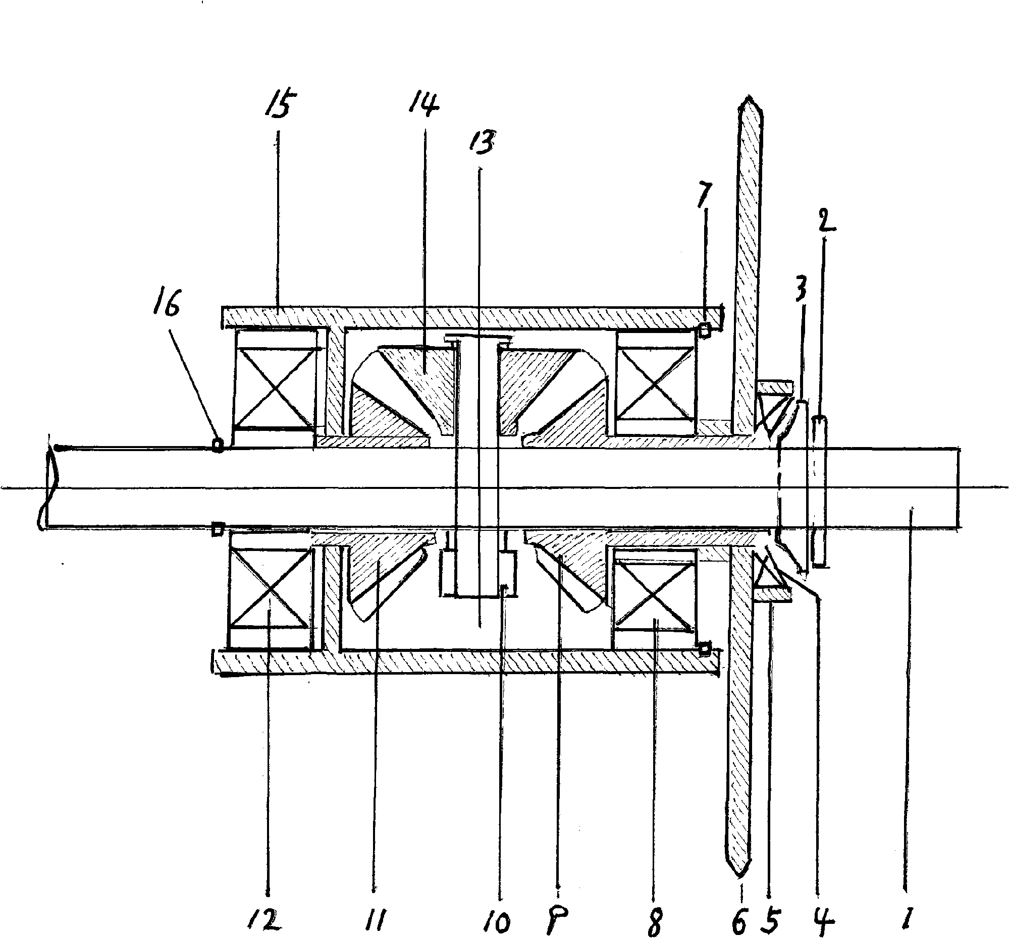
[0007] The pedals are installed on the central shaft 1 and both sides of the continuously variable speed increaser. There are three bevel gears of the same size inside the speed increaser, the left gear 11, the fixed right gear 9, and the floating sleeve on the central shaft of the speed increaser On the outside, Unicom is connected to the central axis wheel disc as a whole in the outer shell 15. Through the power of the pedals, it is transmitted on the central shaft 1, and the central shaft 1 starts to rotate, driving the small central shaft 13, which is also rotating. At the same time, the gear 14, driven by the small central shaft, engages the left gear 11, small When the central shaft rotates one revolution, the gear 14, also rotates itself one revolution at the same time. With this feature, one round of the pedal turns two rounds on the central shaft wheel, so it produces 1 to 2 work efficiency. The speed ratio is increased, so under the control of the foot force, the fu...


PUM


Abstract

The invention relates a speed increaser, which can achieve the stepless speed change function by simple foot driving, belonging to the bicycle field. The speed increaser comprises the parts such as a central axis, a nut, a bearing, a wheel disc, a closing ring, a gear, a shell and a shaft bowl, etc. The speed increaser has the advantages of portable design, safety and comfortableness.

Description

technical field [0001] The invention belongs to the field of bicycles and relates to a simple bicycle pedal speed increaser. Background technique [0002] In traditional bicycles, the speed change is accomplished by the handle twister steel wire, which has a complex structure and general effect. Contents of the invention [0003] The purpose of the present invention is to provide a portable, safe, easy-to-operate, and obvious speed-increasing function, which is a continuously variable speed-increasing gear. After being installed or manufactured in the lower pedal area of ​​the main frame of the bicycle, the speed can be increased or decreased by driving the force of the foot. Description of drawings [0004] The figure is a schematic diagram of the bicycle pedal speed increaser. [0005] The speed increaser includes 1. the central axis of the speed increaser is also the central axis of the pedal. 2. Fix the nut on the center shaft. 3. Outer shaft bowl. 4. Inner shaf...

Claims


Application Information

Patent Timeline
Patent Type & Authority Applications(China)
IPC IPC(8): B62M11/02
Inventor 张补元
Owner 张补元
Learn More