
Conveying device

A conveying device and conveyor belt technology, which is applied in the direction of conveyor objects, transportation and packaging, etc., can solve the problems of oil mist scattering, unsatisfactory sanitation, strong odor, etc., and achieve the effect of suppressing equipment costs

Active Publication Date: 2018-03-13
TOYOTA BOSHOKU KK
View PDF9 Cites 0 Cited by
  • Summary
  • Abstract
  • Description
  • Claims
  • Application Information

AI Technical Summary

Problems solved by technology

However, since the work of turning the oil filter upside down after applying the anti-rust oil is performed manually, an additional work of turning the oil filter upside down is added.
In addition, due to the application of oils and fats, the mist of oils and fats will be scattered in the work site, and the odor will be strong, which is not ideal in terms of sanitation.

Method used


Image

  • Conveying device
  • Conveying device
  • Conveying device

Examples


Embodiment Construction

[0029] The matters shown here are illustrative matters, used to illustrate the embodiments of the present invention, and for the purpose of providing an explanation that is considered to be the most effective and easy to understand the principles and conceptual features of the present invention. In this regard, it is not intended to show the detailed structure of the present invention more than necessary in order to fundamentally understand the present invention. Those skilled in the art can clarify several modes of the present invention according to the description combined with the accompanying drawings. How the above is concretized.

[0030] Hereinafter, a conveying device according to an embodiment of the present invention will be described based on the drawings.

[0031] In this embodiment, an oil filter installed on a vehicle engine and used to remove impurities in the engine oil is exemplified as an article. In the production line of a factory that manufactures oil filters,...


PUM


Abstract

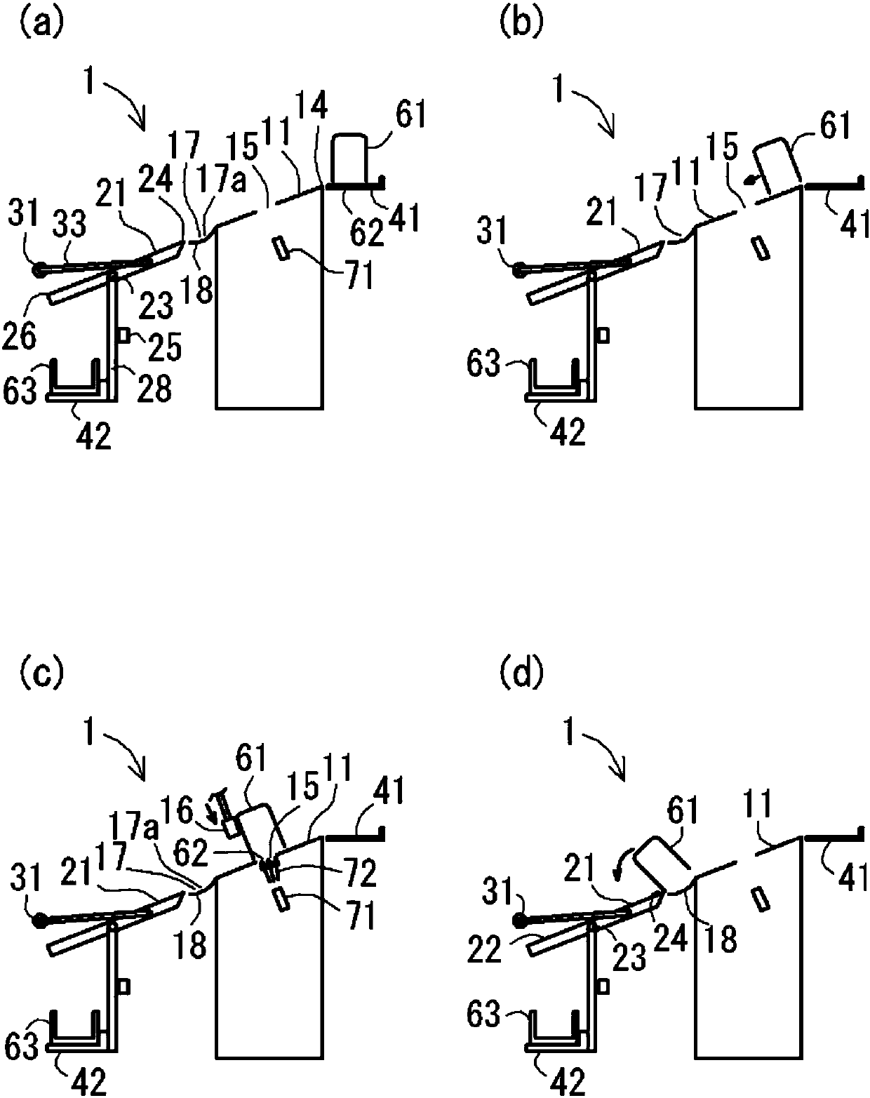
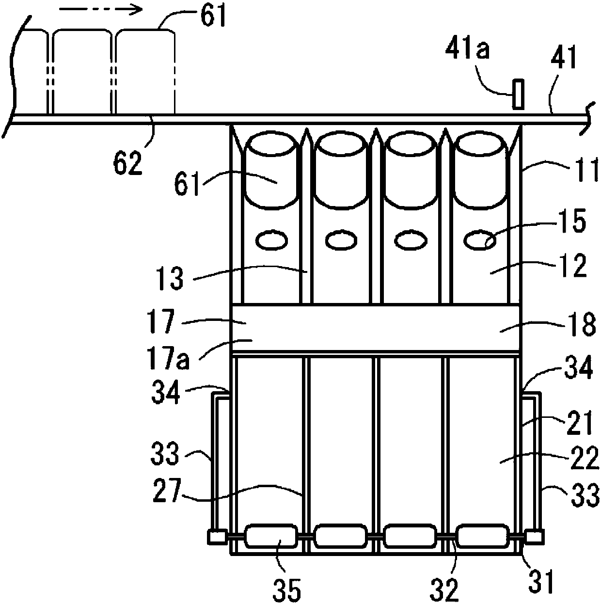
The invention provides a conveying device. The conveying device turns articles over stably and smoothly all the time in the conveying process. The conveying device comprises a first chute (11), a second chute (21), a stop part (31), a conveyor belt (42) and a discharge mechanism (51), wherein the first chute is used for allowing articles supplied to the upper end of the first chute to slide down along the inclined surface under the gravity function; the second chute is arranged below the first chute and is supported by a supporting shaft arranged in the middle portion of the second chute in the inclination direction to rotate freely in the vertical direction and elastically return to the original inclined state after oil filters are discharged; the stop part is arranged at the lower end ofthe second chute, can leave the inclined surface towards the upper portion of the inclined surface of the second chute and is used for abutting against the oil filters falling along the second chuteto prevent the oil filters from falling; the conveyor belt is arranged below the position, wherein the oil filters are discharged, of the second chute and is used for conveying trays for containing the oil filters; the discharge mechanism is used for enabling the stop part to move so as to allow the oil filters to fall.

Description

Technical field [0001] The present invention relates to a conveying device for improving the working efficiency of the process of turning the articles in the middle of the conveying of the articles in a production plant of articles such as oil filters. Background technique [0002] Conventionally, in the production process of an oil filter for a vehicle as an article, an operation is performed in which the oil filter is sprayed and coated with rust preventive oil from below, and then the oil filter is turned upside down and grease is applied from above. However, since the work of turning the oil filter upside down after applying the anti-rust oil is performed manually, the work of turning the oil filter upside down is additionally added. In addition, due to the application of fats and oils, mists of the fats and oils scatter in the work site, resulting in a strong odor, which is not ideal in terms of hygiene. [0003] Therefore, by automating the operation of turning the oil filte...

Claims


Application Information

Patent Timeline
Patent Type & Authority Applications(China)
IPC IPC(8): B65G47/248B65G47/34
CPCB65G47/248B65G47/34
Inventor 冯锦祥徐润添
Owner TOYOTA BOSHOKU KK
Learn More