
Vacuum optical detection system

A technology of optical detection and space optical remote sensing, which is applied in the field of optical detection, can solve the problems of heat dissipation and unusability of interferometers, achieve the effect of simple structure, solve engineering requirements, and facilitate the realization of detection work

Inactive Publication Date: 2018-03-09
CHANGCHUN INST OF OPTICS FINE MECHANICS & PHYSICS CHINESE ACAD OF SCI
View PDF5 Cites 6 Cited by
  • Summary
  • Abstract
  • Description
  • Claims
  • Application Information

AI Technical Summary

Problems solved by technology

Existing interferometers cannot be directly used in a vacuum environment due to the limitations of their internal optical systems and electronic devices, and it is difficult to dissipate heat when the interferometer works in a vacuum environment

Method used


Image

  • Vacuum optical detection system

Examples


Embodiment Construction

[0021] In order to enable those skilled in the art to better understand the solutions of the present invention, the following will clearly and completely describe the technical solutions in the embodiments of the present invention in conjunction with the drawings in the embodiments of the present invention. Obviously, the described embodiments are only It is an embodiment of a part of the present invention, but not all embodiments. Based on the embodiments of the present invention, all other embodiments obtained by persons of ordinary skill in the art without making creative efforts shall fall within the protection scope of the present invention.

[0022] The terms "first", "second", "third", "fourth", etc. (if any) in the description and claims of the present invention and the above drawings are used to distinguish similar objects, and not necessarily Used to describe a specific sequence or sequence. It is to be understood that the terms so used are interchangeable under app...


PUM


Abstract

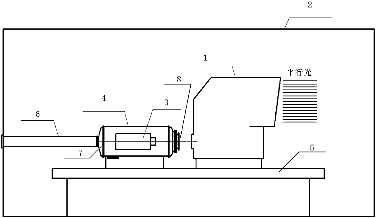
The invention provides a vacuum optical detection system. The vacuum optical detection system comprises a space optical remote senor, a low air pressure simulation device, an interferometer, a vacuumcontainer used for containing the interferometer and an accurate adjustment device used for adjusting the space optical remote senor and the vacuum container, wherein the accurate adjustment device and the vacuum container are contained in the low air pressure simulation device; the low air pressure simulation device is a sealed container with an opening; the vacuum container is in flexible sealedcommunication with the opening through a corrugated pipe; the outside air is communicated with the vacuum container through the opening; the low air pressure simulation device is used for providing environment with low air pressure for the space optical remote senor; the accurate adjustment device is used for adjusting the positions of the space optical remote senor and the vacuum container, so that a focal plane of the space optical remote senor is aligned to a focal plane of the interferometer according to the preset position relation, and then the optical detection of the space optical remote senor under the vacuum environment is achieved.

Description

technical field [0001] The invention relates to the technical field of optical detection, in particular to a vacuum optical detection system. Background technique [0002] Considering that the space optical remote sensor works in a space low-pressure (approximately vacuum) environment, in order to test the performance of its optical system closer to reality, it is best to carry out the detection of the optical system under low-pressure conditions. [0003] Under the existing technical conditions, the detection of space optical remote sensors is generally carried out under laboratory conditions. With the increase of the aperture and focal length of optical remote sensors, the influence of atmospheric disturbance in the laboratory environment on optical detection is increasing. bigger. At present, the influence of atmospheric disturbance on optical system detection can only be reduced by ensuring that the airflow in the laboratory is stable, but it is impossible to fundamenta...

Claims


Application Information

Patent Timeline
Patent Type & Authority Applications(China)
IPC IPC(8): G01M11/04
CPCG01M11/00
Inventor 贾平郭疆李宪斌邵明东朱磊王浩
Owner CHANGCHUN INST OF OPTICS FINE MECHANICS & PHYSICS CHINESE ACAD OF SCI
Learn More