
A large radial displacement margin laser heterodyne interference angle measurement device and method

A technology of laser heterodyne interference and angle measurement, which is applied in the direction of measuring devices, optical devices, instruments, etc., can solve problems such as interferometric interruption, measuring mirror measurement beam deviation, and affecting the normal generation of interference signals, so as to ensure normal generation, Realize the effect of angle measurement and easy package integration

Active Publication Date: 2019-11-15
ZHEJIANG SCI-TECH UNIV
View PDF4 Cites 0 Cited by
  • Summary
  • Abstract
  • Description
  • Claims
  • Application Information

AI Technical Summary

Problems solved by technology

[0003] In order to solve the technical problem that the large radial displacement error of the measuring mirror in the traditional laser interferometry technology causes the measuring beam to deviate from the initial detection aperture on the detector, affecting the normal generation of the interference signal and even causing the interruption of the interferometric measurement, the purpose of the present invention is to provide A large radial displacement margin laser heterodyne interference angle measurement device and method to solve the above problems

Method used


Image

  • A large radial displacement margin laser heterodyne interference angle measurement device and method
  • A large radial displacement margin laser heterodyne interference angle measurement device and method
  • A large radial displacement margin laser heterodyne interference angle measurement device and method

Examples


Embodiment Construction

[0044] The present invention will be further described below in conjunction with drawings and embodiments.

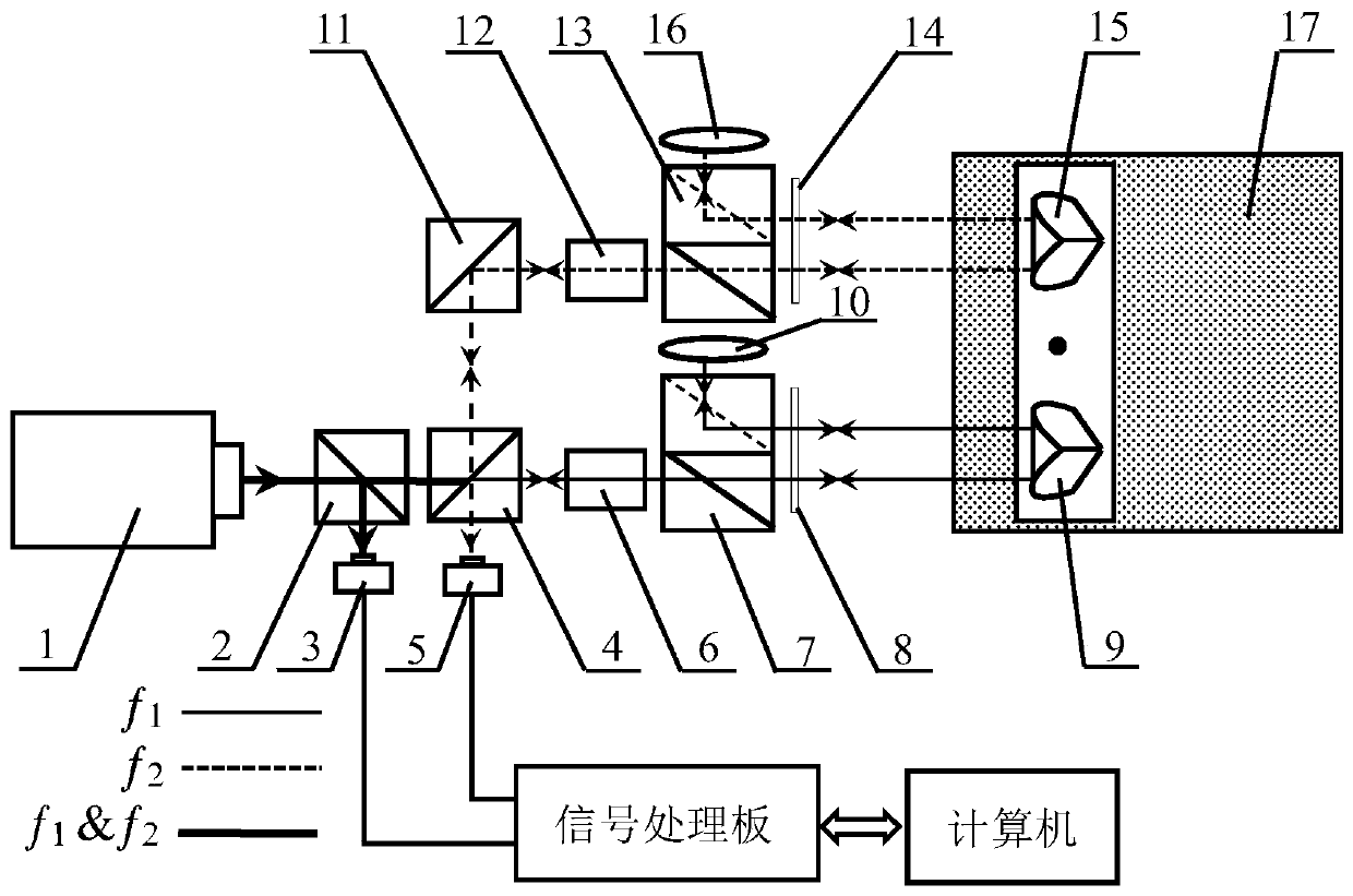
[0045] Optical path structure of the present invention such as figure 1 As shown, the specific implementation process is as follows:

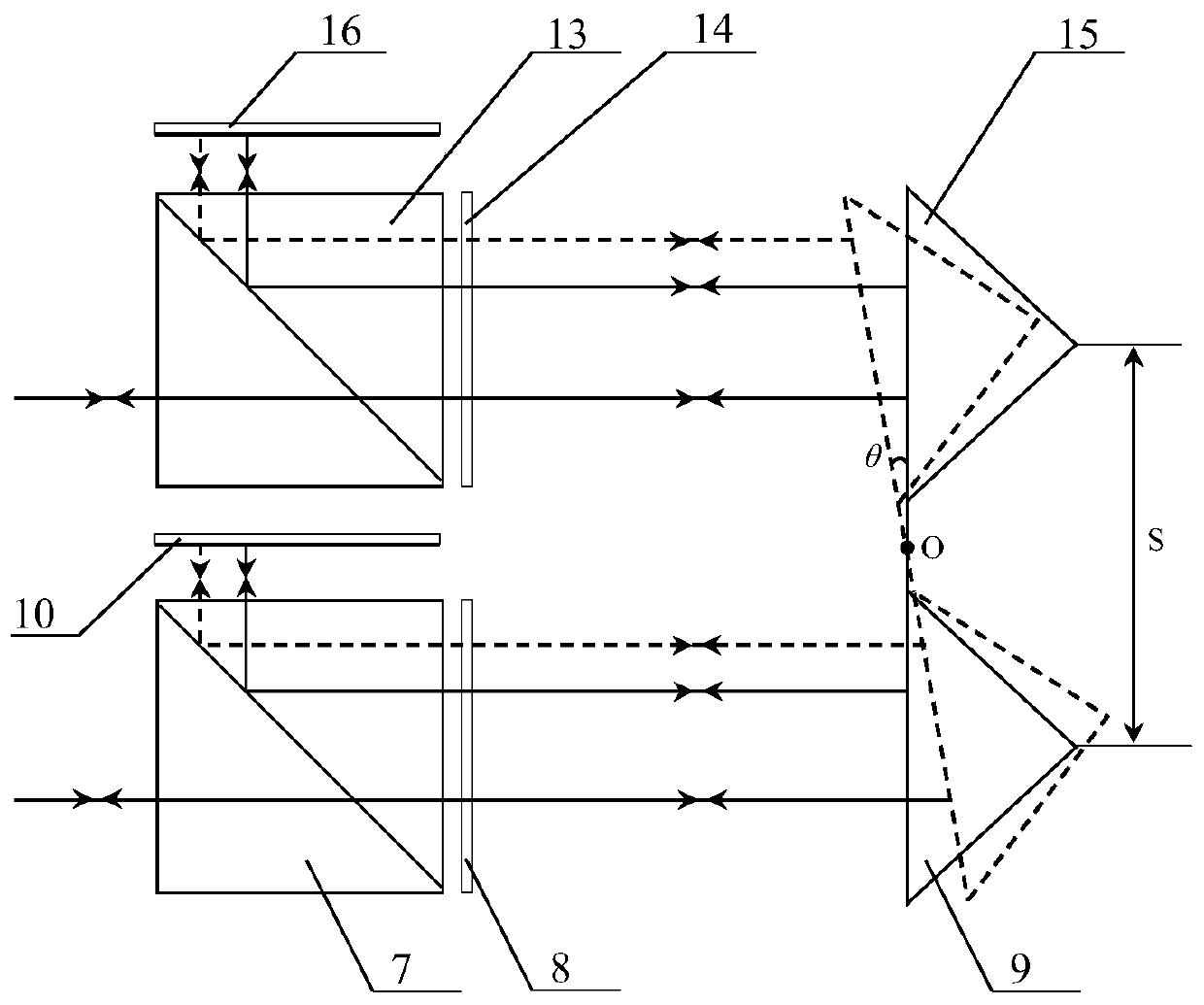
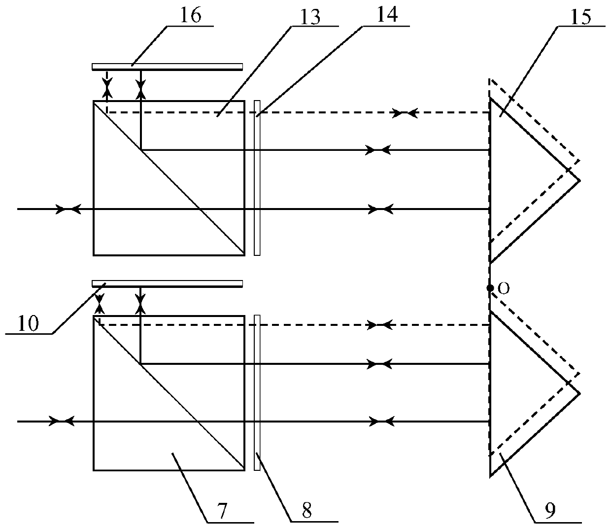
[0046] It includes a laser heterodyne interference angle detection optical path part and an angle measuring mirror. The laser heterodyne interference angle detection optical path part includes a dual-frequency laser 1 outputting orthogonal linearly polarized light, a beam splitter 2, a first photodetector 3, a first polarization beam splitter 4, a second photodetector 5, and a first Faraday rotation light device 6, the first measuring polarizing beam splitter 7, the first quarter-wave plate 8, the first plane mirror 10, the right-angle mirror 11, the second Faraday rotator 12, the second measuring polarizing beam splitting mirror 13, the second The quarter-wave plate 14 and the second plane reflector 16 , wherein the detection apertur...


PUM


Abstract

The present invention discloses a large radial displacement margin type laser heterodyne interference angle measurement device and a method thereof. According to the invention, two faraday rotators are adopted to realize the exact orthogonal transformation of the linearly polarized light in the polarization direction in a laser heterodyne interference angle measurement light path. The device comprises a laser heterodyne interference angle detection light path part and an angle measurement mirror. According to the invention, a light path structure is formed by faraday rotators, a polarization beam splitter, a quarter-wave plate and a plane mirror. Based on the light path structure, when a large radial displacement error occurs in a measurement mirror, the effective return of a measurement light beam is realized. According to the invention, the technical problem in the prior art that based on traditional laser interference measurement mirror angle measurement techniques, the measurementlight beam deviates from an initial detection aperture on a detector, caused by the large radial displacement of the measurement mirror, so as to influence the normal generation of interference signals and even cause the interruption of interference measurement can be solved. The angle measurement of high resolution and large measurement range can be realized. The device and the method are suitable for the angle measurement and calibration of precision operating platforms in the fields of precision machining, manufacturing, mechanical system adjustment, calibration and the like.

Description

technical field [0001] The invention relates to a measuring method characterized by adopting an optical method, in particular to a large radial displacement margin laser heterodyne interference angle measuring device and method. Background technique [0002] The motion attitude of a space object can be described by six degrees of freedom, including three translations along an axis and three rotations around an axis. Angle measurement is an important part of precision geometric measurement technology. The realization of angle measurement with high resolution and large measurement range is the position calibration and adjustment of mechanical systems, processing and manufacturing in the field of advanced manufacturing, and precision measurement and calibration in the field of metrology. Waiting to realize the improvement of the technical level and the common needs of scientific and technological innovation. Laser interferometry is widely used in the precise measurement of ang...

Claims


Application Information

Patent Timeline
Patent Type & Authority Patents(China)
IPC IPC(8): G01B11/26
CPCG01B11/26
Inventor 张恩政陈本永
Owner ZHEJIANG SCI-TECH UNIV
Learn More