Method of using auxiliary marker to improve building three-dimensional scanning definition

A three-dimensional scanning, sharpness technology, applied in the direction of using optical devices, measuring devices, instruments, etc., can solve problems such as point cloud fogging, boundary recognition effects, etc.

Active Publication Date: 2018-03-09
SHANGHAI BAOYE GRP CORP
View PDF4 Cites 0 Cited by
  • Summary
  • Abstract
  • Description
  • Claims
  • Application Information

AI Technical Summary

Problems solved by technology

[0003] In the process of 3D scanning of building steel structures, the interface and bolt holes are often affected by factors such as scanning distance, scanning angle, and steel surface roughness...

Method used


Image

  • Method of using auxiliary marker to improve building three-dimensional scanning definition
  • Method of using auxiliary marker to improve building three-dimensional scanning definition

Examples


Embodiment Construction

[0016] The present invention is further illustrated below by specific examples.

[0017] A method for improving the clarity of building three-dimensional scanning by using auxiliary markers, comprising

[0018] Step 1. Determine whether the boundary of the component to be scanned is an external boundary or an internal boundary;

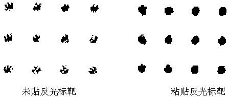
[0019] Step 2. Paste the reflective strip;

[0020] Step 2.1. For the outer boundary, paste reflective stickers with high reflectivity along the outer circle of the boundary to increase the point cloud intensity at the location of the stickers; at the same time, for component surfaces with low reflectivity and smooth surfaces, paste reflective stickers on the entire scanning surface , to increase the point cloud intensity of the entire surface;

[0021] Step 2.2. For the inner boundary, paste a reflective target that can form a mirror reflection on the back of the bolt hole to reduce the point cloud intensity of the target position;

[0022] Step 3...


PUM


Abstract

The invention particularly relates to a method of using an auxiliary marker to improve building three-dimensional scanning definition. The method is characterized by comprising steps: a boundary in need of component scanning is determined to be whether an outer boundary or an inner boundary; a reflective strip is pasted; as for the outer boundary, a reflective strip with high reflectivity is pasted along the outer circle of the boundary, and the point cloud intensity at the strip position is improved; as for the inner boundary, pasting on the back surface of a bolt hole can form a reflective target of mirror reflection, and the point cloud intensity at the target position is reduced; and the components are scanned, the contrast of the point cloud intensities at two sides of the boundary isincreased through strengthening or weakening the surface point cloud intensity, and the boundary recognition ability is thus improved. The working method uses the auxiliary marking tool to improve the scanning precision in the building steel structure pre-assembly field and other three scanning fields.

Description

technical field [0001] The invention relates to the field of building structure measurement, in particular to a method for improving the clarity of building three-dimensional scanning by using auxiliary markers. Background technique [0002] Three-dimensional scanning is affected by the uneven reflection characteristics of the surface of the scanned object. The higher the reflectivity, the stronger the laser echo signal, and the stronger the intensity of the scanned point cloud, otherwise the lower the intensity of the point cloud. Point cloud recognition is carried out by comparing the point cloud intensity on both sides of the boundary. The greater the point cloud intensity contrast at the boundary, the easier it is to identify the boundary. If the point cloud intensity contrast on both sides is not obvious, the boundary is not easy to identify. [0003] In the process of 3D scanning of building steel structures, the interface and bolt holes are often affected by factors s...

Claims


Application Information

Patent Timeline
IPC IPC(8): G01B11/24
CPCG01B11/24
Inventor 李维民罗兴隆潘斯勇
Owner SHANGHAI BAOYE GRP CORP
Why Eureka
Try Eureka