
combine harvester

A combine harvester and machine body technology, which is applied to harvesters, cutters, agricultural machinery and implements, etc., can solve the problems of deformation of the right wall and narrow maintenance space of the threshing device, and achieve the effect of easy maintenance

Active Publication Date: 2022-02-25
ISEKI & CO LTD
View PDF10 Cites 0 Cited by
  • Summary
  • Abstract
  • Description
  • Claims
  • Application Information

AI Technical Summary

Problems solved by technology

[0006] However, in the technique of Patent Document 1, since the exhaust gas purification device is arranged on the inclined portion formed on the upper right wall of the threshing device, the maintenance space of the threshing device is narrowed, and there is a problem caused by the vibration of the exhaust gas purification device during driving. The problem of deforming the right wall of the threshing device due to

Method used


Image

  • combine harvester
  • combine harvester
  • combine harvester

Examples


Embodiment Construction

[0037] The present invention will be described with reference to the accompanying drawings. In addition, from the operator's point of view, directions are simply indicated by describing the front as the front, the rear as the rear, the right-hand as the right, and the left-hand as the left.

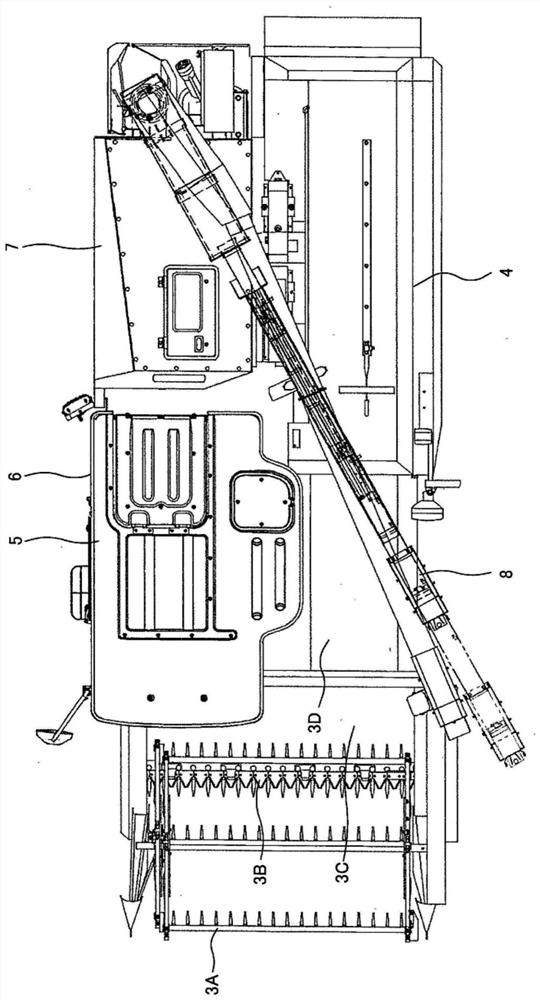
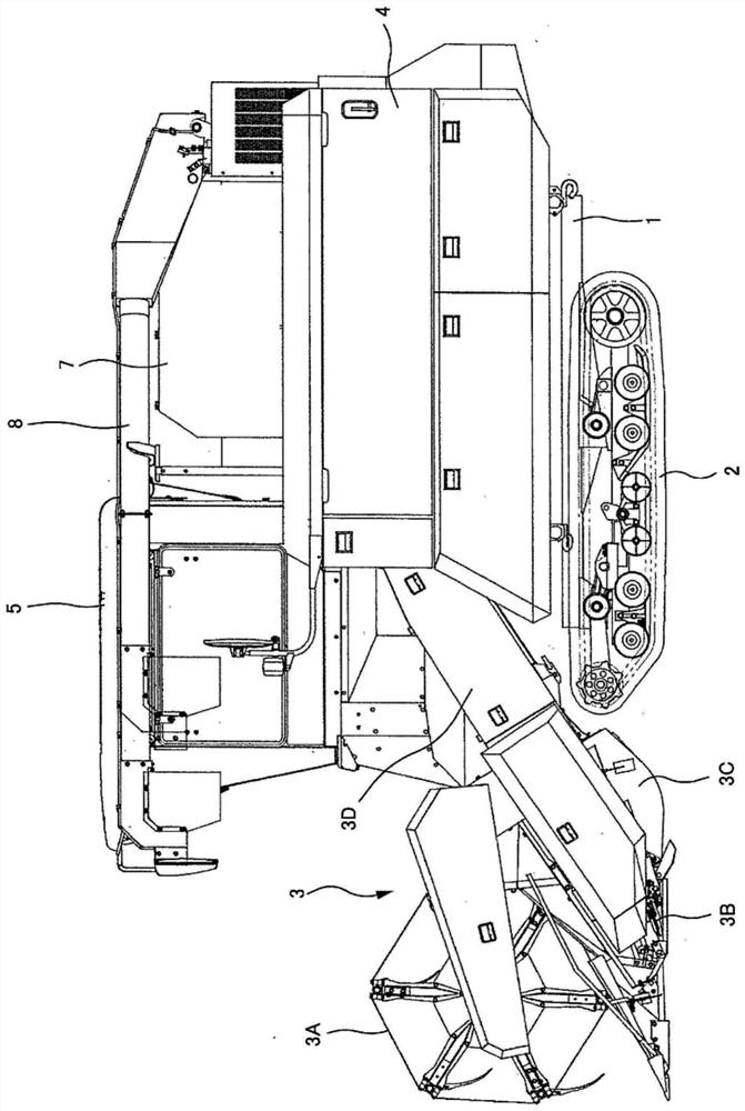
[0038] Such as figure 1 , 2 Shown, with regard to general-purpose combine harvester, the underside of body frame 1 is provided with the traveling device 2 that is made of left and right pair of caterpillars that travels on the soil surface, is provided with harvesting farmland on the front side of body frame 1. The harvesting pre-processing device 3 of the grain stalk is provided with a threshing device 4 for threshing / screening the harvested grain stalks at the rear left part of the harvesting pre-processing device 3, and is provided with a rear right part of the harvesting pre-processing device 3. The control unit 5 for the operator to take.

[0039] The lower side of the control par...


PUM


Abstract

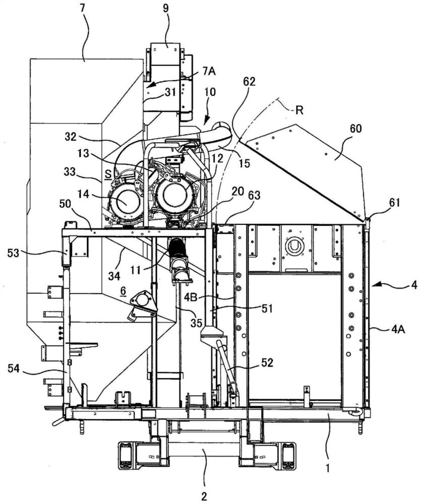
The present invention provides a combine capable of easily performing maintenance of a threshing device and preventing deformation of the right wall of the threshing device. The exhaust pipe (15) connected to the exhaust port of the purification device (14) extends upward from the purification device (14), extends to the left at the front side of the lifting device (9), and The left side of the lifting device (9) extends to the rear side, and the processing cylinder cover (60) of the threshing device (4) is rotatably supported on the left wall (4A) of the threshing device (4). The support shaft (61) of the front-rear direction provided on the top is set at a position where the rotation track of the right side end of the processing cylinder cover (60) avoids the exhaust pipe (15).

Description

technical field [0001] The present invention relates to a combine harvester provided with an exhaust purification device. Background technique [0002] In a conventional combine harvester, it is known that an exhaust purification device is disposed in the space between the inclined portion formed on the upper right wall of the threshing apparatus and the cutout portion formed on the left wall of the grain tank (Patent Document 1). . [0003] prior art literature [0004] patent documents [0005] Patent Document 1: Japanese Patent Laid-Open No. 2015-123051 [0006] However, in the technique of Patent Document 1, since the exhaust gas purification device is arranged on the inclined portion formed on the upper right wall of the threshing device, the maintenance space of the threshing device is narrowed, and there is a problem caused by the vibration of the exhaust gas purification device during driving. Waiting for the deformation of the right wall of the threshing device....

Claims


Application Information

Patent Timeline
Patent Type & Authority Patents(China)
IPC IPC(8): A01D41/12B60K13/04
CPCA01D41/1252B60K13/04A01D41/12A01F12/18
Inventor 山本次郎中井正司渡部宽树二神伸
Owner ISEKI & CO LTD
Learn More