
Cascade type optical cable monitoring method and system based on optical time division technology

A monitoring system and cascading technology, applied in transmission systems, electromagnetic wave transmission systems, selection devices of multiplexing systems, etc., can solve problems such as difficulty in locating fault points, many optical cable sections, and large quantities, and shorten the fault period. The effect of processing time, improving operational reliability, and reducing construction costs

Pending Publication Date: 2018-03-06
STATE GRID JIANGSU ELECTRIC POWER CO XUZHOU POWER SUPPLY CO +1
View PDF4 Cites 0 Cited by
  • Summary
  • Abstract
  • Description
  • Claims
  • Application Information

AI Technical Summary

Problems solved by technology

[0002] At present, with the advancement of distribution automation construction, a large number of distribution optical fiber communication lines have been put into operation, which is characterized by a large number, many optical cable sections, heavy daily operation and maintenance of optical cables, and difficulties in real-time monitoring and troubleshooting.
According to the traditional operation and maintenance mode, if the line fails, it is difficult to locate the fault point, which seriously affects the reliable operation of the communication network

Method used


Image

  • Cascade type optical cable monitoring method and system based on optical time division technology
  • Cascade type optical cable monitoring method and system based on optical time division technology
  • Cascade type optical cable monitoring method and system based on optical time division technology

Examples


Embodiment Construction

[0022] The present invention will be further described through specific embodiments below in conjunction with the accompanying drawings.

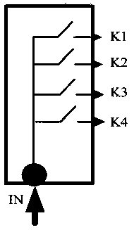
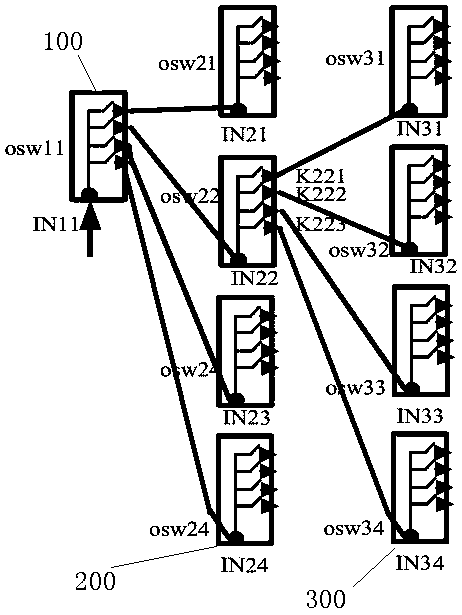
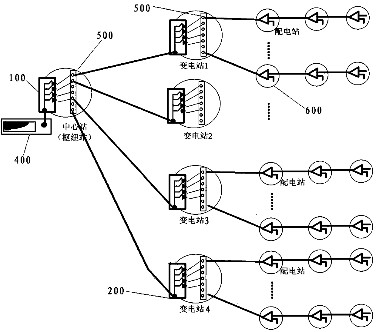
[0023] A cascaded optical cable monitoring method based on optical time-division technology. The monitoring light sent by a test instrument is realized through an optical switch, and sent to the corresponding port in time intervals. A level of optical switch is cascaded under each output port. The sent monitoring light is allocated to the corresponding output port in smaller time slots again, and so on. Using this optical switch cascading method, it is possible to realize a comprehensive monitoring instrument to poll different optical cables in different substations in a time-sharing manner or Roll call monitoring.

[0024] At a certain moment, the optical power of the test instrument is all allocated to one of the ports, while the other ports have no light, so as to ensure the intensity of the test light and realize the test of long-distan...


PUM


Abstract

The invention discloses a cascade type optical cable monitoring method based on an optical time division technology. The method is characterized in that monitoring light is emitted by one instrument through an optical switch, and the monitoring light is sent to corresponding ports at different time intervals; a first-stage optical switch is cascaded below each output port; the smaller time interval is distributed to the transmitted monitored light to the corresponding output ports again, by analogy, one comprehensive monitoring instrument carries out polling type or roll-call type monitoring on different optical cables of different substations at different time buckles through an optical switch cascading mode, so that the use efficiency of the instrument is greatly improved. The monitoringmethod can be applied to an online optical cable monitoring system, and the system construction cost and the operation and maintenance cost are reduced, a large number of optical cables can be conveniently and efficiently monitored, and the operation and maintenance working efficiency and the management level of the optical cables can be improved.

Description

technical field [0001] The invention relates to a cascaded optical cable monitoring method and monitoring system based on optical time division technology, which are mainly used in the communication field, and specifically applied in the optical cable operation and maintenance and monitoring fields. Background technique [0002] At present, with the advancement of distribution automation construction, a large number of distribution optical fiber communication lines have been put into operation, which is characterized by a large number, many optical cable sections, heavy daily operation and maintenance of optical cables, and difficulties in real-time monitoring and troubleshooting. According to the traditional operation and maintenance mode, if the line fails, it is difficult to locate the fault point, which seriously affects the reliable operation of the communication network. Contents of the invention [0003] According to the deficiencies of the prior art, the present in...

Claims


Application Information

Patent Timeline
Patent Type & Authority Applications(China)
IPC IPC(8): H04B10/077H04Q11/00
CPCH04B10/0771H04Q11/0003H04Q11/0005H04Q11/0062H04Q2011/0007H04Q2011/0083
Inventor 李正超李倩张歆滕松冯守沛朱信刚陆飞飞唐杰杰刘英
Owner STATE GRID JIANGSU ELECTRIC POWER CO XUZHOU POWER SUPPLY CO
Learn More