
Power conversion circuit and associated operating method

A power conversion and circuit technology, which is applied to the conversion device of output power, conversion of DC power input to DC power output, high-efficiency power electronic conversion, etc. Effect

Inactive Publication Date: 2018-03-06
MEDIATEK INC
View PDF5 Cites 0 Cited by
  • Summary
  • Abstract
  • Description
  • Claims
  • Application Information

AI Technical Summary

Problems solved by technology

When the size of the resonant device becomes smaller, the power handling performance of the power conversion circuit may deteriorate

Method used


Image

  • Power conversion circuit and associated operating method
  • Power conversion circuit and associated operating method
  • Power conversion circuit and associated operating method

Examples


Embodiment Construction

[0019] Certain terms are used throughout the specification and following claims to refer to particular components. Those skilled in the art should understand that hardware manufacturers may use different terms to refer to the same component. This description and the following claims do not use the difference in name as a way to distinguish components, but use the difference in function of components as a criterion for distinguishing. The "comprising" mentioned in the entire description and the following claims is an open-ended term, so it should be interpreted as "including but not limited to". In addition, the word "coupling" here includes any direct and indirect electrical connection means. Therefore, if it is described in the text that a first device is coupled to a second device, it means that the first device can be directly electrically connected to the The second device, or indirectly electrically connected to the second device through other devices or connection means...


PUM


Abstract

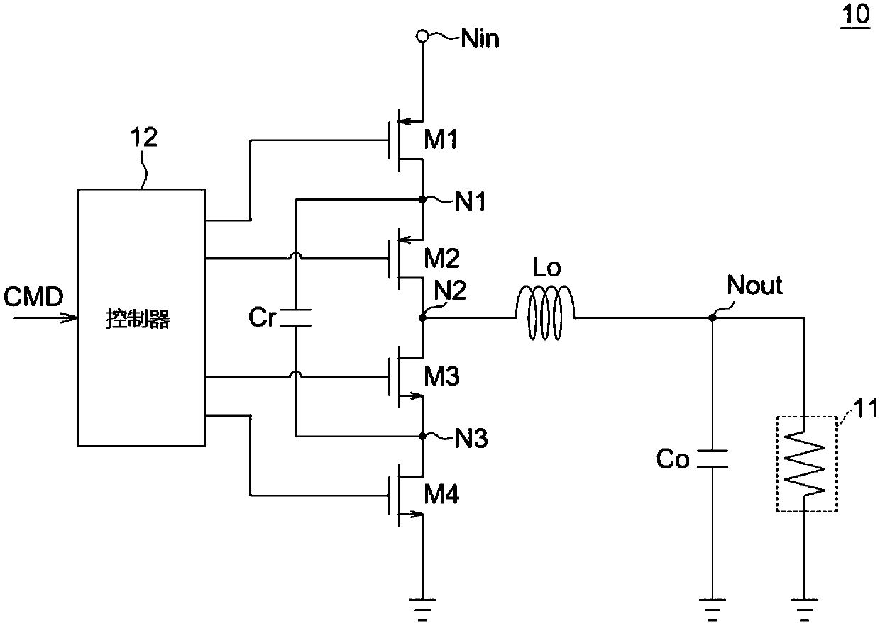
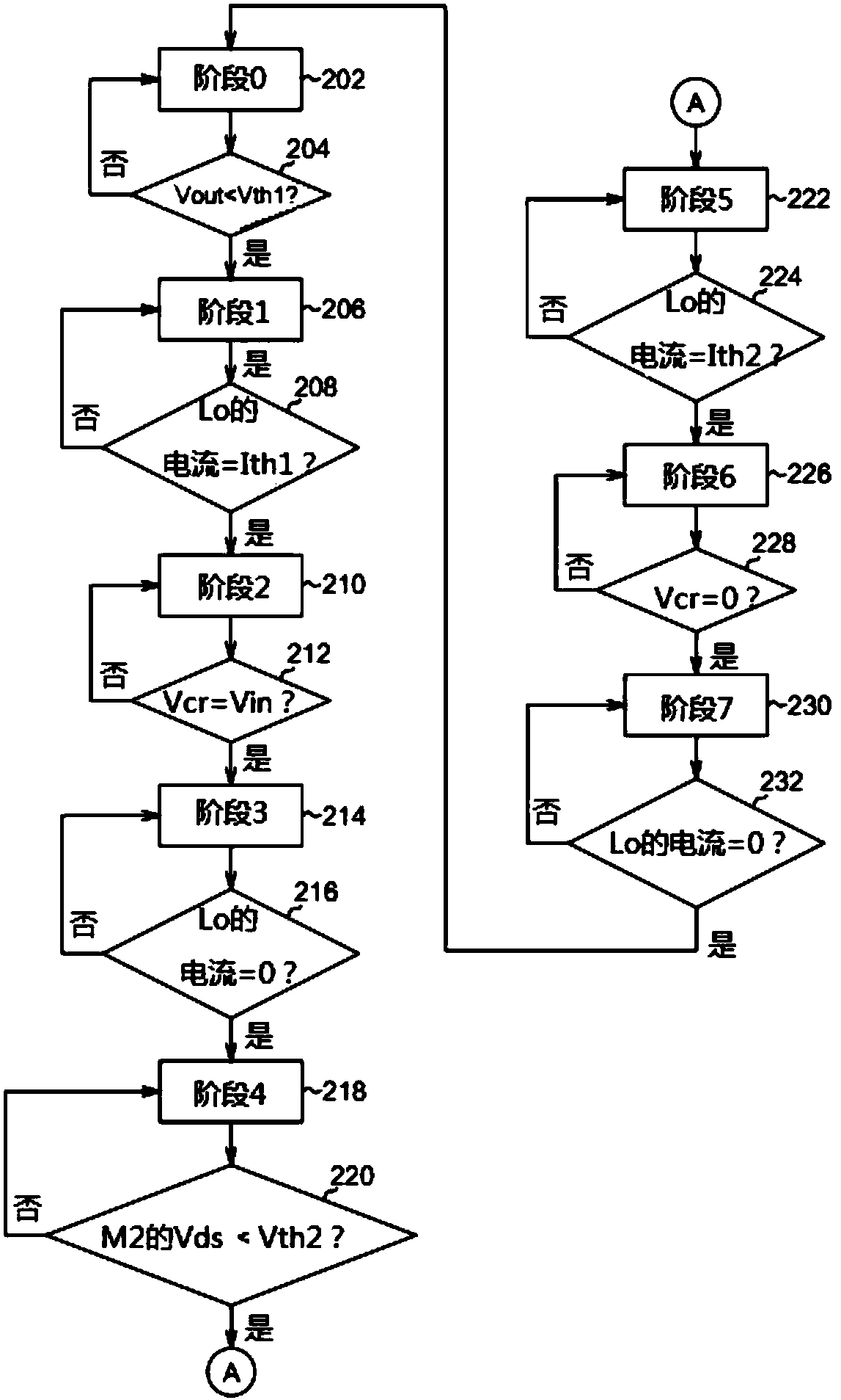
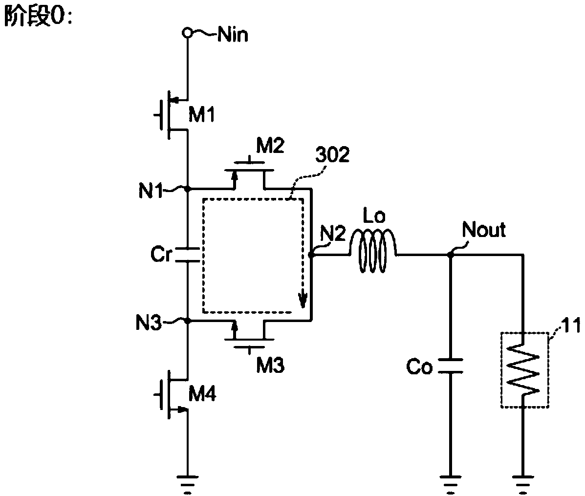
A power conversion circuit includes an input terminal, a first switching element, a second switching element, a third switching element, a fourth switching element, a capacitor; an inductor; and a controller configured to control the switching elements to be switched ON / OFF, such that a voltage at the load is regulated by repetitively (1) charging the inductor with a first current before chargingthe capacitor causing a second current to flow in the inductor and (2) charging the inductor with a third current before discharging the capacitor causing a fourth current to flow in the inductor. Thefirst switching element comprises a pair of first ends between the input end and a first node, and a first control end. The second switching element comprises a pair of second ends between the firstnode and a second node, and a second control end. The third switching element comprises a pair of third ends between the second node and a third node, and a third control end. The fourth switching element comprises a pair of fourths ends between the third node and ground, and a fourth control end. The capacitor is between the first node and the third node. The inductor is between the second node and a load.

Description

【Technical field】 [0001] The invention relates to the technical field of power conversion, in particular to a power conversion circuit and a method for operating the power conversion circuit. 【Background technique】 [0002] A wide variety of electronic devices, such as computers and mobile phones, are powered by a stable DC power source. A power conversion circuit, such as a DC-DC converter, converts a high voltage input from a battery or another power source to a desired output voltage by switching transistors to charge or discharge a capacitor. [0003] As electronic devices become smaller, lighter and more compact, there is a need to improve the size and performance of dedicated power conversion circuits. Increasing the switching frequency of power conversion circuits has become a major existing solution to reducing the size and cost of large passive devices. However, as the switching frequency of the power conversion circuit increases, the switching loss also increases...

Claims


Application Information

Patent Timeline
IPC IPC(8): H02M3/158
CPCH02M3/158Y02B70/10H02M1/0009H02M1/0058H02M1/0048H02M1/08
Inventor 陈佐民管建葳徐研训
Owner MEDIATEK INC
Learn More