Life detection device
A technology of life detection and life detector, which is applied in the field of life detection, can solve problems such as limited use conditions and environmental interference, and achieve the effects of improving accuracy, ensuring personal safety, and improving detection accuracy
- Summary
- Abstract
- Description
- Claims
- Application Information
AI Technical Summary
Problems solved by technology
Method used
Image
Examples
Embodiment 1
[0024] Such as Figure 1-3 The shown life detection device includes a main body 1, an infrared thermal imager 5 and a radar life detector 6 are arranged in the main body 1, a chassis 2 and a track wheel mechanism 3 connected to the chassis 2 are arranged at the bottom of the main body 1, and the chassis 2 Two obstacle removal mechanisms 4 are arranged on it.
[0025] The obstacle removal mechanism 4 includes a first obstacle removal arm 7, a second obstacle removal arm 8 and an obstacle removal grasper 9 connected in sequence. The first obstacle removal arm 7 is movably connected to the chassis 2, and the chassis 2 is provided with a driving first obstacle removal arm. The driving motor A10 for the rotation of the arm 7, and the driving motor B11 for driving the rotation of the second obstacle removal arm 8 is arranged on the first obstacle removal arm 7.
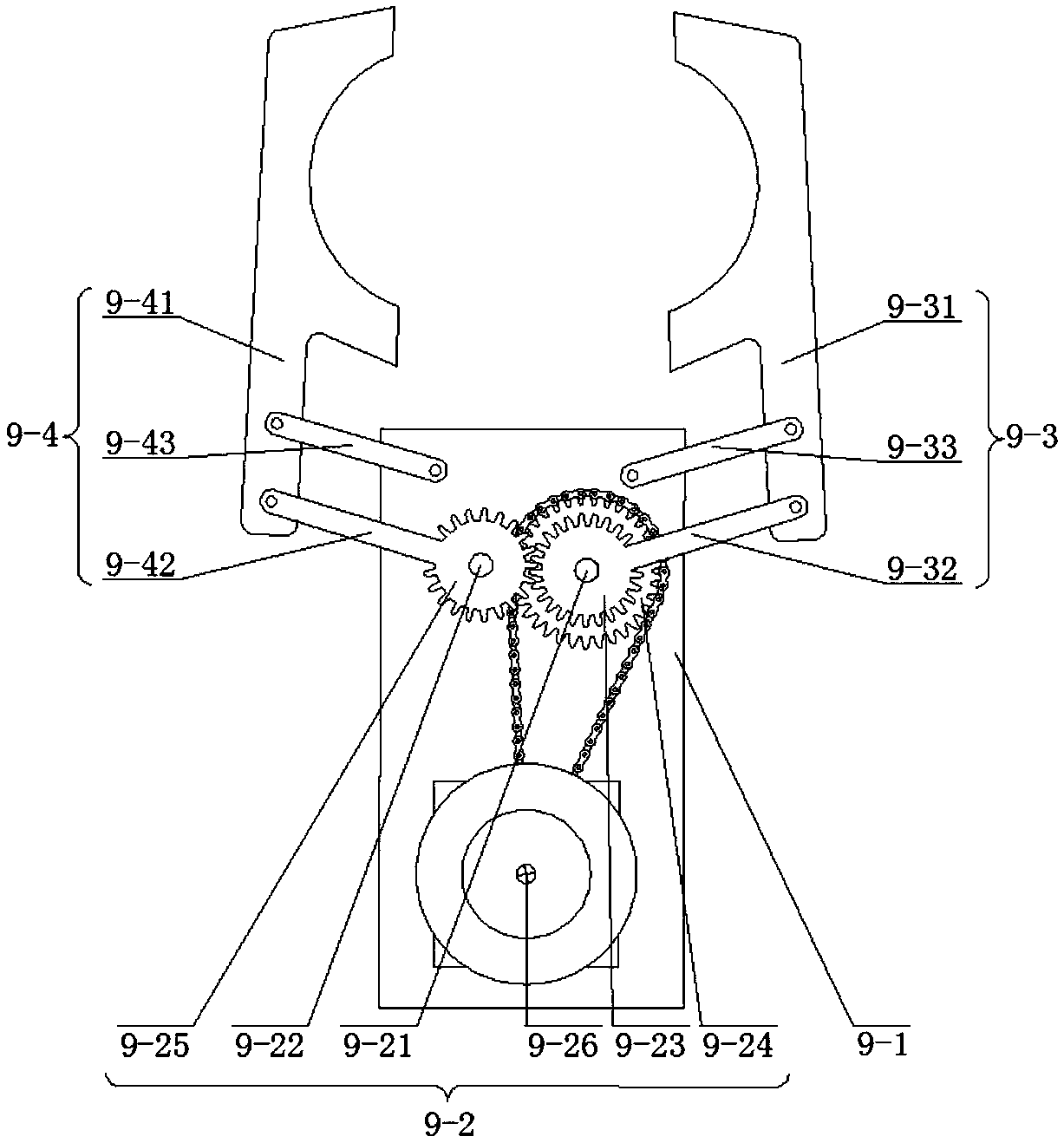
[0026] The obstacle removal grasper 9 includes a support frame 9-1, a gear drive assembly 9-2, a mechanical finger A9-3 ...
Embodiment 2
[0033] The present embodiment has been further optimized on the basis of embodiment 1, specifically:
[0034] Such as Figure 4 As shown, the crawler wheel mechanism 3 includes a front wheel shaft 3-1, a rear wheel shaft 3-2, and two fixing parts 3-3, and the two ends of the fixing parts 3-3 are movably sleeved on the front wheel shaft 3-1 and the rear wheel shaft 3-3 respectively. 2, the front wheel shaft 3-1 is provided with two front wheels 3-4 and secondary sprocket 3-5, and the rear wheel shaft 3-2 is provided with two rear wheels 3-6 and driving sprocket B3-7. The front wheel 3-4 on the side and the rear wheel 3-6 are covered with a crawler belt 3-13, and a chain 3-8 is provided between the driving sprocket B3-7 and the secondary sprocket 3-5; 3 is also provided with a drive motor D3-9 for driving the rear wheel shaft 3-2 to rotate; two support rods 3-3 are vertically provided with support rods 3-10, and the two support rods 3-10 connect the fixed parts 3-3 is connecte...
Embodiment 3
[0039] The present embodiment has been further optimized on the basis of embodiment 1, specifically:
[0040] Such as Figure 5 As shown, the radar life detector 6 includes a radar detection control terminal 6-1, a radar transmitter 6-2, a launch controller 6-3, a radar receiver 6-4, a receiving controller 6-5, and a data processing terminal 6- 6. The input end of the radar detection control terminal 6-1 is connected to the output end of the radar receiver 6-4, and the output end of the detection control terminal is connected to the emission controller 6-3, the receiving controller 6-5 and the data processing terminal 6-6 The input end of the radar receiver 6-4 is connected to the output end of the receiving controller 6-5, and the input end of the radar detection control terminal 6-2 is connected to the output end of the launch controller 6-3. The radar detection control terminal 6-1, the transmitting controller 6-3, the receiving controller 6-5, and the data processing term...
PUM
 Abstract
Description
Claims
Application Information
 - R&D Engineer
- R&D Manager
- IP Professional
- Industry Leading Data Capabilities
- Powerful AI technology
- Patent DNA Extraction
Browse by: Latest US Patents, China's latest patents, Technical Efficacy Thesaurus, Application Domain, Technology Topic, Popular Technical Reports.
© 2024 PatSnap. All rights reserved.Legal|Privacy policy|Modern Slavery Act Transparency Statement|Sitemap|About US| Contact US: help@patsnap.com


