A vertical arm of a truss type missile
What is Al technical title?
Al technical title is built by PatSnap Al team. It summarizes the technical point description of the patent document.
A vertical arm and truss-type technology, applied in the direction of the launch device, can solve the problems of large processing volume, heavy weight, and small load-bearing section, and achieve the effect of small mass, high support strength, and increased bending section size
Active Publication Date: 2020-08-07
BEIJING INST OF SPACE LAUNCH TECH +1
View PDF5 Cites 0 Cited by
Summary
Abstract
Description
Claims
Application Information
AI Technical Summary
This helps you quickly interpret patents by identifying the three key elements:
Problems solved by technology
Method used
Benefits of technology
Problems solved by technology
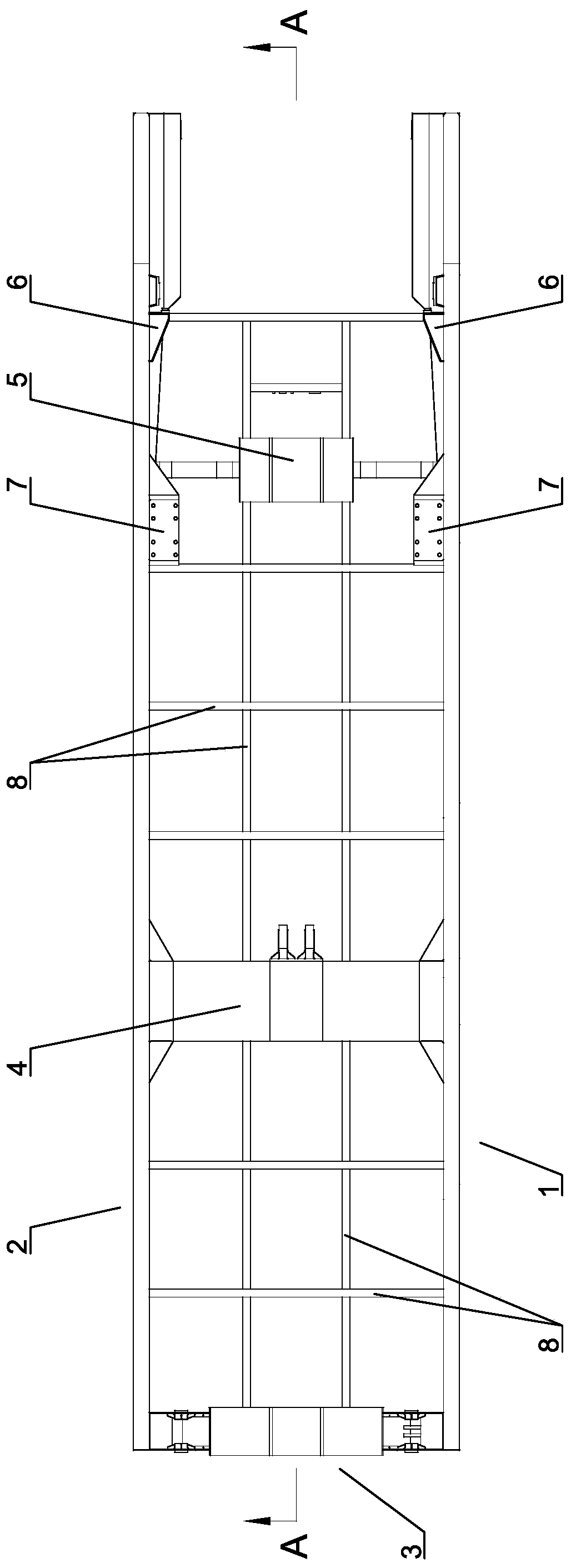
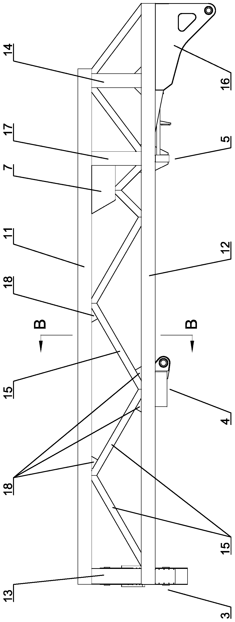
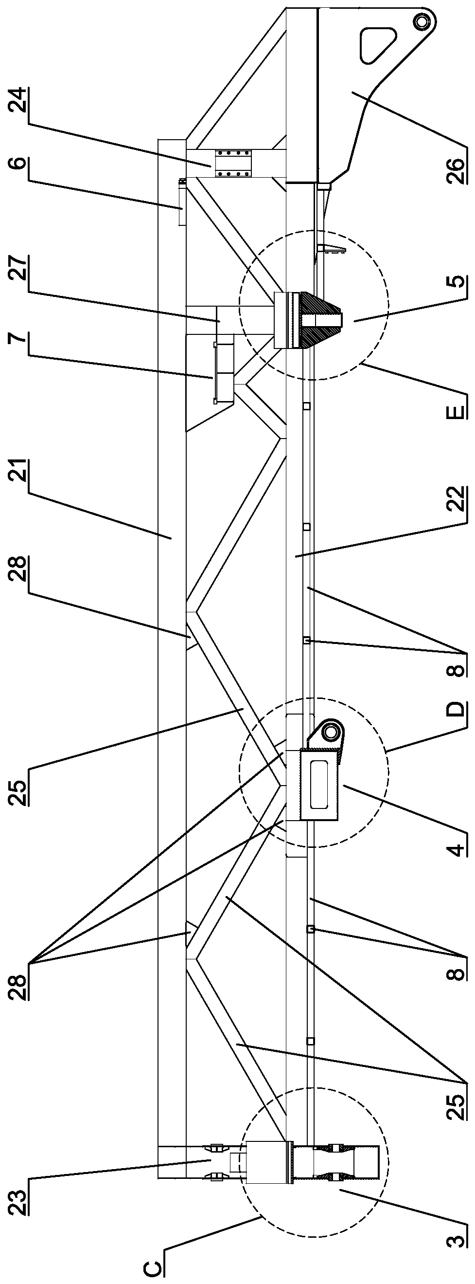
[0004] In order to solve the problems of heavy weight, small load-bearing section and large processing volume of the missile vertical arm in the prior art, the present invention provides a truss-type missile vertical arm, which includes relative distribution and is a truss structure. The left arm body and the right arm body, the front support assembly, the erection assembly and the rear support assembly are arranged at intervals from front to back between the left arm body and the left arm body, and the left arm body includes a left upper beam and a left lower beam, and the left upper beam The front and rear ends of the beam and the left lower beam are correspondingly fixed by welding the left front vertical beam and the left rear vertical beam, and a plurality of left diagonal brace beams are also welded between the left upper beam and the left lower beam; the right arm body includes a right upper beam and a right lower beam, The front and rear ends of the upper right beam and the lower right beam are correspondingly fixed by welding the right front vertical beam and the right rear vertical beam, and a plurality of right diagonal brace beams are also welded between the right upper beam and the right lower beam; the rear ends of the left lower beam and the right lower beam correspond to There are fixed left swivel lugs and right swivel lugs; among them, the left upper beam, left lower beam, left front vertical beam, left rear vertical beam, left diagonal brace beam, right upper beam, right lower beam, right front vertical beam, right rear vertical beam and right oblique The support beams are all made of high-strength steel square tubes; the left and right swivel lugs are made of high-strength steel plates for tailor welding
Method used
Image
Click on the blue label to locate the original text in one second.
Reading with bidirectional positioning of images and text.
[0030] Such as Figure 1 to Figure 13 所示本发明一种桁架式导弹起竖臂的具体实施方式,包括相对分布且均为桁架结构的左臂体1和右臂体2。在左臂体1和左臂体2之间由前至后间隔设置前支撑组件3、起竖组件4和后支撑组件5。左臂体1具体包括左上梁11和左下梁12,让左上梁11和左下梁12的前后端对应通过左前竖梁13和左后竖梁14焊接固定,并在左上梁11和左下梁12之间焊接多个左斜撑梁15。右臂体2具体包括右上梁21和右下梁22,让右上梁21和右下梁22的前后端对应通过右前竖梁23和右后竖梁24焊接固定,并在右上梁21和右下梁22之间焊接多个右斜撑梁25。同时,在左下梁12和右下梁22的后端对应焊接固定左回转耳16和右回转耳26。让左上梁11、左下梁12、左前竖梁13、左后竖梁14、左斜撑梁15、右上梁21、右下梁22、右前竖梁23、右后竖梁24和右斜撑梁25均采用高强钢方管制作,让左回转耳16和右回转耳26均采用高强钢板进行拼焊。
[0031] Through the above structural settings, a truss type missile vertical arm with simple structure, easy preparation, small mass, high supporting strength, safety and reliability is formed. In practical application, the present invention adopts the truss structure of double-layer bearing beams for both the left arm body 1 and the right arm body 2, and increases the distance between the left upper beam 11 and the left lower beam 12 in the left arm body 1 and the righ...
PUM
Abstract
The invention relates to a truss type guided missile erecting arm comprising a left arm body and a right arm body. A front supporting assembly, an erecting assembly and a back supporting assembly arearranged at intervals from front to back between the left arm body and the right arm body. The left arm body comprises a left upper beam and a left lower beam. The front ends and the back ends of theleft upper beam and the left lower beam are correspondingly welded and fixed through a left front vertical beam and a left back vertical beam. Multiple left diagonal bracing beams are welded between the left upper beam and the left lower beam. The right arm body comprises a right upper beam and a right lower beam. The front ends and the back ends of the right upper beam and the right lower beam are welded and fixed through a right front vertical beam and a right back vertical beam. Multiple right diagonal bracing beams are welded between the right upper beam and the right lower beam. A left rotation lug and a right rotation lug are correspondingly fixed to the back end of the left lower beam and the back end of the right lower beam. The truss type guided missile erecting arm has the advantages of being simple in structure, easy to manufacture, light in weight, high in supporting strength, safe and reliable, the lightening purpose can be achieved, the machiningworkload can be reduced,the quality of the finished product is improved, and the bearing capacity is guaranteed.
Description
technical field [0001] 本发明涉及一种导弹起竖臂,具体涉及一种桁架式、轻质化的导弹起竖臂。 Background technique [0002] 在武器车载热发射领域,在导弹停放、运输、起竖和回抱过程中,通常采用起竖臂带动导弹以完成起竖、回落动作。导弹起竖臂需要具备足够的强度,以支撑导弹并承受导弹重力等惯性载荷。目前本领域使用的导弹起竖臂主要采用普通焊接结构钢的单层主梁结构,在实际应用中还存在储多问题,主要表现在以下方面:主要依靠单层主梁承受载荷,承受载荷的截面较小,且因主体材料的屈服点较低,通常采用提高材料壁厚(8mm~16mm)的方式来保证强度,很容易造成导弹起竖臂自身的重量较大;没有针对不同承载位置的材料壁厚进行合理优化,也没有针对应力集中的部位进行处理,既造成了材料浪费,也增大了导弹起竖臂的整体重量;现有导弹起竖臂上的限位结构主要采用固定式结构,在总装时需要根据实际生产和安装公差进行结构的修磨或贴补,不但操作复杂而且难以控制;因导弹起竖臂为单层主梁结构,各组成零部件的形状较大且不规则,需采用大量钢板拼焊完成工作,无法直接使用型材,造成了导弹起竖臂的焊缝较多,加工量较大,起竖臂质量和承载能力无法得到有效保证。 Contents of the invention [0003] 本发明的目的是提供一种桁架式导弹起竖臂,其具有结构简单、制备容易、质量较小、支撑强度大、安全可靠的优点,可实现轻质化目的,并可降低加工量,提高成品质量,保证承载能力。 [0004] 为解决现有技术中的导弹起竖臂其存在的重量较大、承载截面小、加工量较大的问题,本发明提供的一种桁架式导弹起竖臂,包括相对分布且均为桁架结构的左臂体和右臂体,左臂体和左臂体之间由前至后间隔设有前支撑组件、起竖组件和后支撑组件,所述左臂体包括左上梁和左下梁,左上梁和左下梁的前后端对应通过左前竖梁和左后竖梁焊接固定,左上梁和左下梁之间还焊接有多个左斜撑梁;所述右臂体包括右上梁和右下梁,右上梁和右下梁的前后端对应通过右前竖梁和右后竖梁焊接固定,右上梁和右下梁之间还焊接有多个右斜撑梁;左下梁和右下梁的后端对应固定有左回转耳和右回转耳;其中,左上梁、左下梁、左前竖梁、左后竖梁、左斜撑梁、右上梁、右下梁、右前竖梁、右后竖梁和右斜撑梁均采用高强钢方管制作;所述左回转耳...
Claims
Application Information
Patent Timeline
Application Date:The date an application was filed.
Publication Date:The date a patent or application was officially published.
First Publication Date:The earliest publication date of a patent with the same application number.
Issue Date:Publication date of the patent grant document.
PCT Entry Date:The Entry date of PCT National Phase.
Estimated Expiry Date:The statutory expiry date of a patent right according to the Patent Law, and it is the longest term of protection that the patent right can achieve without the termination of the patent right due to other reasons(Term extension factor has been taken into account ).
Invalid Date:Actual expiry date is based on effective date or publication date of legal transaction data of invalid patent.
