


Quick Research
Generate reliable direction feasibility study reports for your R&D in just a few steps.

Technical Q&A
Discover and master advanced knowledge NOW. Basics, ideas, possibilities, all at once.

Find Solutions
As an expert in R&D theories, this can generate solutions to your technical problems instantly.

Evaluate Feasibility
Analyze your overall solution with one click, know your potential R&D risks in advance.

Monitor Landscape
Get weekly tech updates, stay abreast of the latest tech innovations and key insights.
Gas-supply gas circuit and method guaranteeing remote control online redundancy of multiple pneumatic valves
A pneumatic valve and air circuit technology, applied in the direction of valve operation/release device, valve device, valve details, etc., to achieve the effect of improving reliability and reducing risk
- Summary
- Abstract
- Description
- Claims
- Application Information
AI Technical Summary
Problems solved by technology
Method used
Image

Examples
Embodiment 1
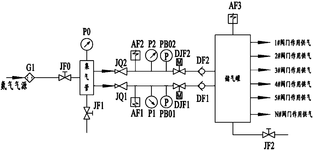
[0033] like figure 1 As shown in the figure, the present invention discloses a remote-controlled online redundant air supply circuit for ensuring a plurality of pneumatic valves. There is an air source cut-off valve JF0 on the pipeline connecting the air inlet end of the air pipe with the air source. Air supply can be realized by manually opening the air source cut-off valve JF0, and a filter is set on the pipeline between the air source and the air source cut-off valve JF0. The device G1 is used to filter excess matter. In this embodiment, the gas source is a nitrogen gas source, and the gas collecting pipe is arranged in a circular structure as a whole to play a role of voltage stabilization. Three pressure gauges P0; the gas collecting pipe has a first gas outlet end and a second gas outlet end, the gas storage tank has a first gas inlet end and a second gas inlet end, and the first gas outlet end and the first gas inlet end pass through the first gas The second gas outlet...
Embodiment 2
[0038] like figure 1 , 2 As shown, based on the same inventive concept as the first embodiment, the present embodiment discloses a remote-controlled online redundant gas supply method for ensuring multiple pneumatic valves by utilizing the above-mentioned gas supply gas path. The gas method includes the following steps:
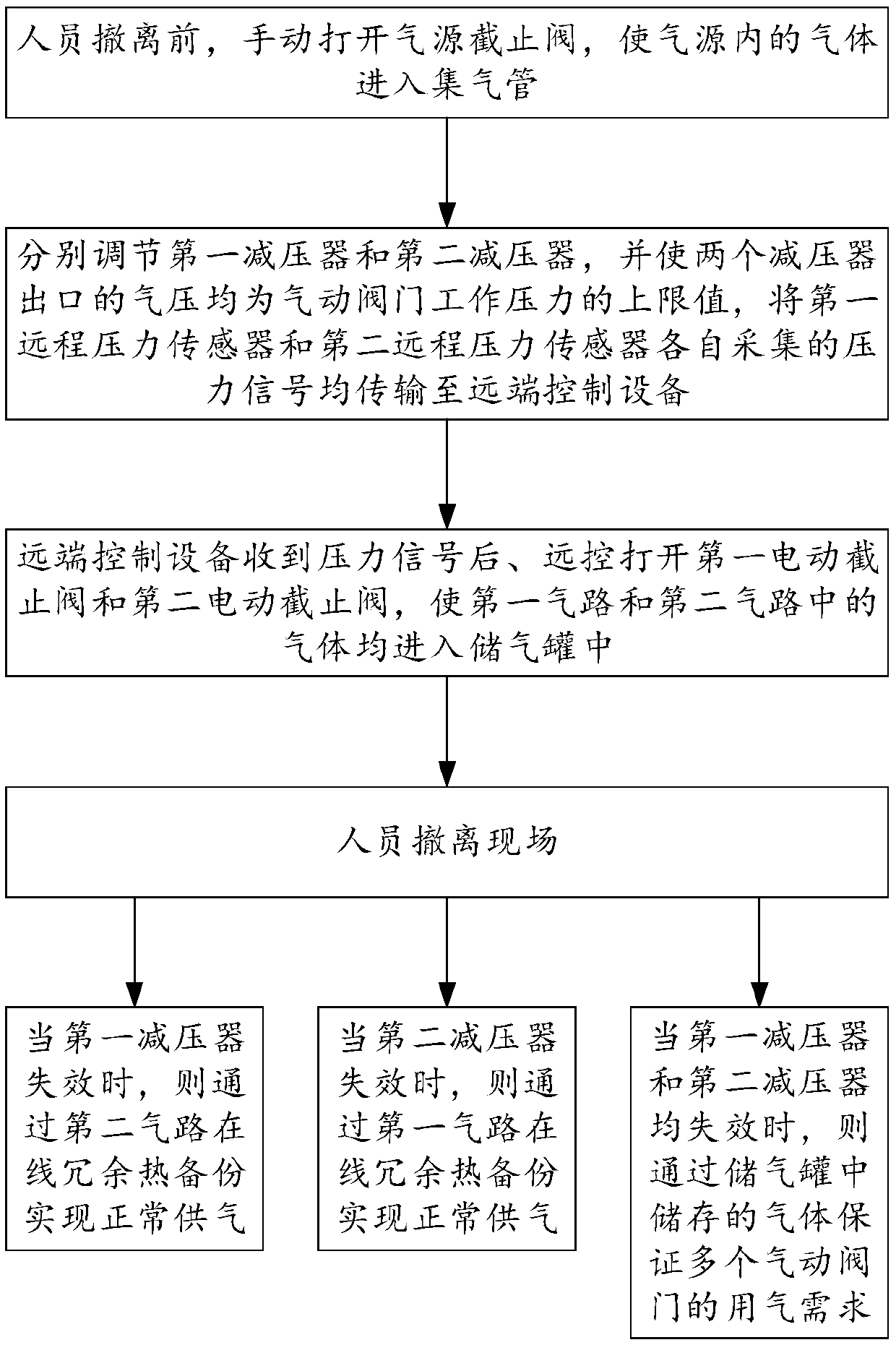
[0039] Step 1. Before the personnel are evacuated, manually open the gas source shut-off valve JF0, then the high-pressure nitrogen gas passes through the filter G1 to achieve the purpose of making the gas in the gas source enter the gas collecting pipe. The gas source pressure displayed on the third pressure gauge P0 is p0 .
[0040] Step 2, adjust the first pressure reducer JQ1 and the second pressure reducer JQ2 respectively, and make the air pressure at the outlet of the two pressure reducers be the upper limit P of the working pressure of the pneumatic valve. 上 , the air pressure displayed on the first pressure gauge P1 is p1, the air pressure display...
PUM
 Abstract
Description
Claims
Application Information
 - R&D Engineer
- R&D Manager
- IP Professional
- Industry Leading Data Capabilities
- Powerful AI technology
- Patent DNA Extraction
Browse by: Latest US Patents, China's latest patents, Technical Efficacy Thesaurus, Application Domain, Technology Topic, Popular Technical Reports.
© 2024 PatSnap. All rights reserved.Legal|Privacy policy|Modern Slavery Act Transparency Statement|Sitemap|About US| Contact US: help@patsnap.com