
Soot deposition body manufacturing apparatus and manufacturing method

A technology for manufacturing devices and stacking bodies, which is applied in the direction of manufacturing tools, glass manufacturing equipment, glass deposition furnaces, etc., and can solve problems such as particle peeling

Pending Publication Date: 2018-03-06
SHIN ETSU CHEM IND CO LTD
View PDF6 Cites 5 Cited by
  • Summary
  • Abstract
  • Description
  • Claims
  • Application Information

AI Technical Summary

Problems solved by technology

[0004] Sometimes the fine particles that accumulate on the outer side of the side torch will flake off

Method used


Image

  • Soot deposition body manufacturing apparatus and manufacturing method
  • Soot deposition body manufacturing apparatus and manufacturing method
  • Soot deposition body manufacturing apparatus and manufacturing method

Examples


Embodiment Construction

[0019] Hereinafter, the present invention will be described through embodiments of the invention. The following embodiments do not limit the invention of the claims. In addition, not all combinations of features described in the embodiments are essential to the solution means of the invention.

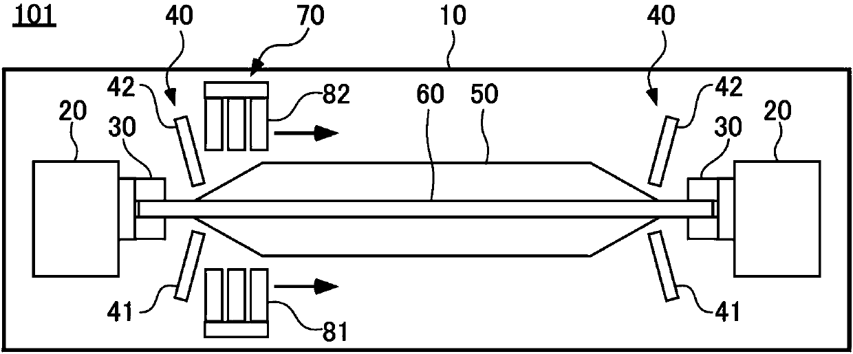
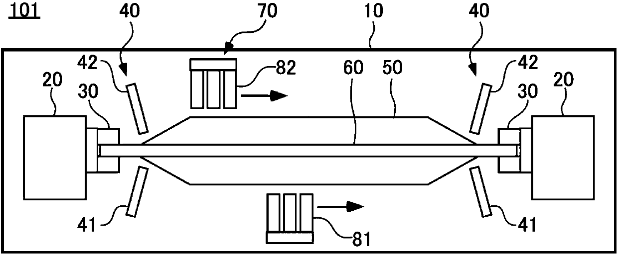
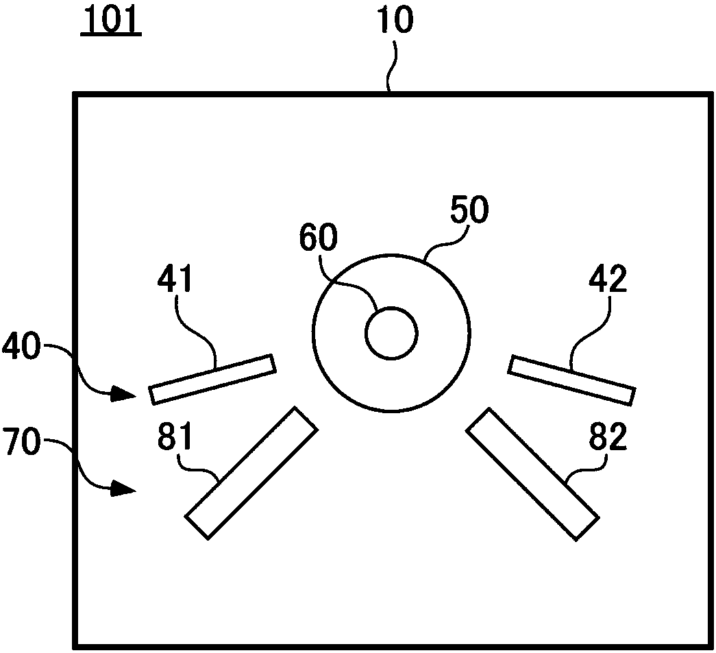
[0020] figure 1 It is a schematic horizontal cross-sectional view showing an example of a manufacturing apparatus 101 for manufacturing a powder accumulation body. The manufacturing apparatus 101 has a chamber 10 , a rotating mechanism 20 , a chuck 30 , a side torch 40 , and a main torch 70 .

[0021] In the vicinity of both ends in the longitudinal direction inside the chamber 10 , a rotating mechanism 20 and chucks 30 are arranged respectively. The pair of chucks 30 are respectively supported rotatably relative to the chamber 10 and hold both ends of the target rod 60 . The rotating mechanism 20 rotates the target rod 60 held by the chuck 30 by rotating the chuck 30 .

[0022] T...


PUM


Abstract

Provided is a manufacturing apparatus for manufacturing a soot deposition body, including a main burner that deposits glass microparticles on a target rod while moving parallel to a longitudinal direction of the target rod; and a side burner that is positioned outside of a movement range of the main burner in a movement direction of the main burner, and fires an end portion of the soot depositionbody formed on the target rod. The side burner includes a plurality of heating burners arranged distanced from each other in a circumferential direction of the target rod. In the manufacturing apparatus described above, the main burner may include a plurality of deposition burners that are arranged distanced from each other in the circumferential direction of the target rod. The manufacturing apparatus improves yield of the soot deposition body.

Description

technical field [0001] The present invention relates to a manufacturing device and a manufacturing method of a powder accumulation body. Background technique [0002] When powder deposits are formed during the manufacturing process of the base material for optical fiber, there is a technique to prevent powder deposits from being partially damaged by arranging side torches near both ends of the deposits and firing the powder deposits at that part. The exfoliated powder exfoliates (refer to Patent Document 1). [0003] Patent Document 1: Japanese Patent Laid-Open No. 2003-165738 [0004] Sometimes the fine particles accumulated on the outer side of the side torch will flake off. Contents of the invention [0005] According to a first aspect of the present invention, there is provided a manufacturing apparatus for manufacturing a powder accumulation body, comprising: a main torch that deposits glass particles on a target while moving in parallel along the longitudinal direc...

Claims


Application Information

Patent Timeline
IPC IPC(8): C03B37/018
CPCC03B37/01853C03B37/0142C03B37/0148C03B2207/64C03B2207/54C03B2207/66C03B19/1423C03B19/1492C03B37/01493C03B2207/62C03B2207/81
Inventor 柏木佑介弥永富久
Owner SHIN ETSU CHEM IND CO LTD
Learn More