
Shaft steel wire baffle ring mounting tool

A steel wire retaining ring and installation tool technology, applied in the direction of manufacturing tools, hand-held tools, etc., can solve the problems of difficult installation, scratched shaft surface, improper installation method, etc., to achieve simple structure, convenient use, and solve the risk of scratching. Effect

Pending Publication Date: 2018-03-06
天津市百成油田采油设备制造有限公司
View PDF0 Cites 1 Cited by
  • Summary
  • Abstract
  • Description
  • Claims
  • Application Information

AI Technical Summary

Problems solved by technology

[0003] In view of this, the present invention aims to propose a shaft steel wire retaining ring installation tool to solve the problem of difficult installation and scratching the shaft surface caused by improper installation methods when the steel wire retaining ring is installed on the shaft surface

Method used


Image

  • Shaft steel wire baffle ring mounting tool
  • Shaft steel wire baffle ring mounting tool
  • Shaft steel wire baffle ring mounting tool

Examples


Embodiment Construction

[0025] It should be noted that, in the case of no conflict, the embodiments of the present invention and the features in the embodiments can be combined with each other.

[0026] In describing the present invention, it should be understood that the terms "center", "longitudinal", "transverse", "upper", "lower", "front", "rear", "left", "right", The orientations or positional relationships indicated by "vertical", "horizontal", "top", "bottom", "inner", "outer", etc. are based on the orientation or positional relationships shown in the drawings, and are only for the convenience of describing the present invention Creation and simplification of description, rather than indicating or implying that the device or element referred to must have a specific orientation, be constructed and operate in a specific orientation, and therefore should not be construed as limiting the invention. In addition, the terms "first", "second", etc. are used for descriptive purposes only, and should no...


PUM


Abstract

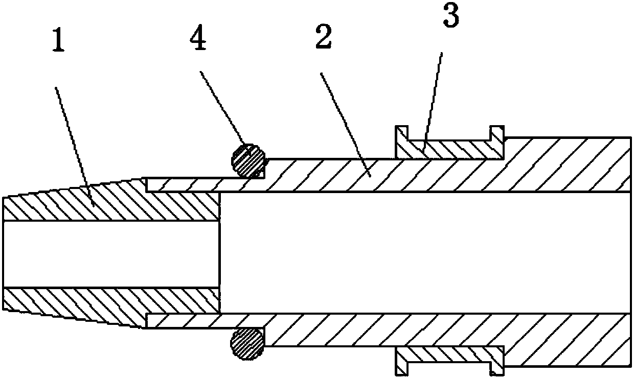
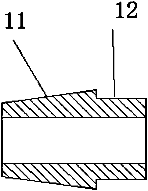
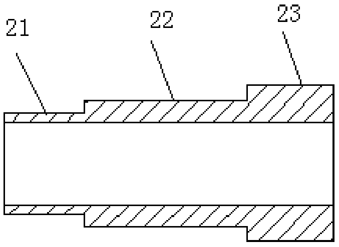
The invention creatively provides a shaft steel wire baffle ring mounting tool. The tool comprises a guide-in sleeve, a pre-installing sleeve and a push-installing sleeve; the pre-installing sleeve comprises a sleeving part arranged at one end and a pushing moving part tightly adjacent to the sleeving part; the guide-in sleeve comprises a guide part and a mounting part, the mounting part is inserted in an inner hole of the pre-installing sleeve and is detachably connected with the pre-installing sleeve, and the push-installing sleeve is movably arranged on the pushing moving part in a sleevingmanner, and is used for enabling a steel wire baffle ring to be pushed and moved to a shaft through the sleeving part. The shaft steel wire baffle ring mounting tool is simple in design structure andconvenient to use, the steel wire baffle ring can be supported open through the sleeving part, the scratch risk caused by hand supporting can be avoided, meanwhile, moving of the steel wire baffle ring can be finished through the pre-installing sleeve, a gap is reserved between the pre-installing sleeve and the surface of the shaft, and therefore when the steel wire baffle ring slides and is conveyed on the shaft, the shaft surface cannot be scratched, and the use quality of the shaft surface is protected.

Description

technical field [0001] The invention belongs to the technical installation field of steel wire retaining rings installed on the shaft surface, and in particular relates to an installation tool for steel wire retaining rings for shafts. Background technique [0002] In the design of electric submersible pumps, a large number of shaft steel wire retaining rings are used as the positioning of parts on the shaft. Due to the design requirements, the rigidity and strength of this wire retaining ring are very high. When used in the assembly process of the submersible electric pump, the assembler first needs to break the steel wire retaining ring to an appropriate size with bare hands for installation, and this process can easily cause damage to the assembler's fingers. When the steel wire retaining ring is installed from one end of the shaft, it needs to be pushed axially into the designated positioning groove along the shaft body. During this process, the end face of the retainin...

Claims


Application Information

Patent Timeline
IPC IPC(8): B25B27/00B25B27/14
CPCB25B27/00B25B27/14
Inventor 田有义高虹王雅然
Owner 天津市百成油田采油设备制造有限公司
Learn More