
A clamping device in the process of tire transportation

A conveying process and clamping device technology, which is applied in the direction of conveyors, conveyor objects, transportation and packaging, etc., can solve the problems of high manufacturing and conveying costs, complex clamping device structure, and affecting the efficiency of conveying workpieces, so as to reduce manufacturing costs. and transportation costs, simple structure, and easy maintenance

Active Publication Date: 2020-09-25
湖北迪迈威智能装备有限公司
View PDF6 Cites 5 Cited by
  • Summary
  • Abstract
  • Description
  • Claims
  • Application Information

AI Technical Summary

Problems solved by technology

[0008] This application provides a clamping device in the process of tire transportation to solve the problems that the existing clamping device has a complex structure, high manufacturing and transportation costs, inconvenient maintenance for workers, and greatly affects the efficiency of conveying workpieces.

Method used


Image

  • A clamping device in the process of tire transportation
  • A clamping device in the process of tire transportation
  • A clamping device in the process of tire transportation

Examples


Embodiment 2

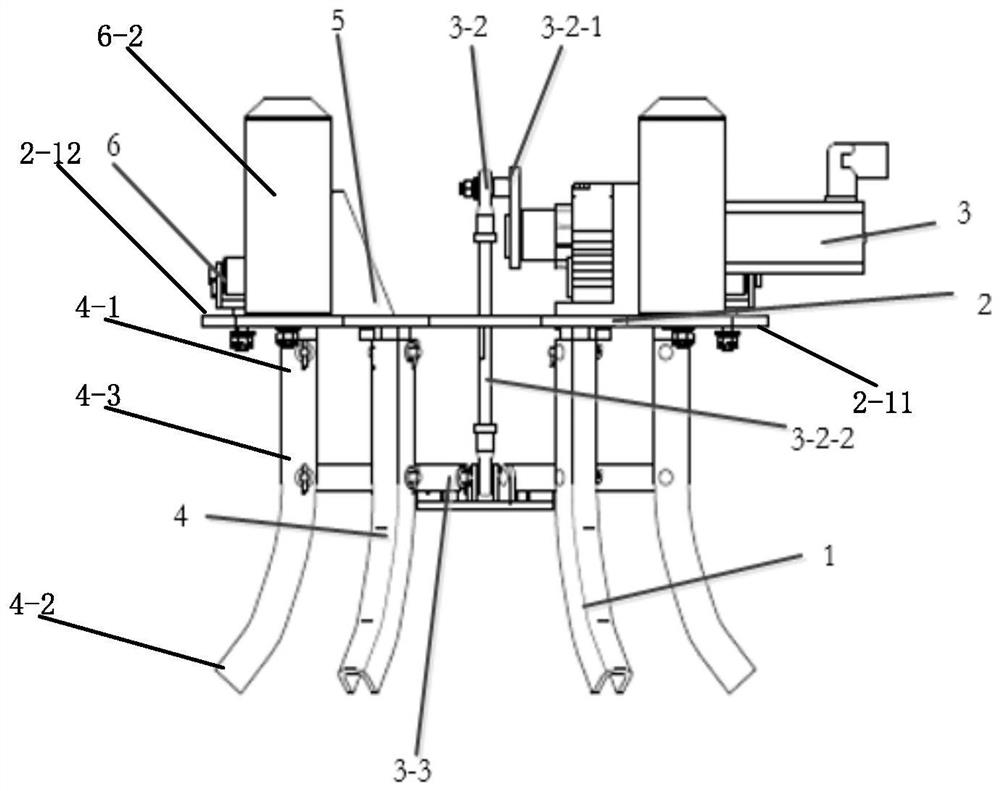
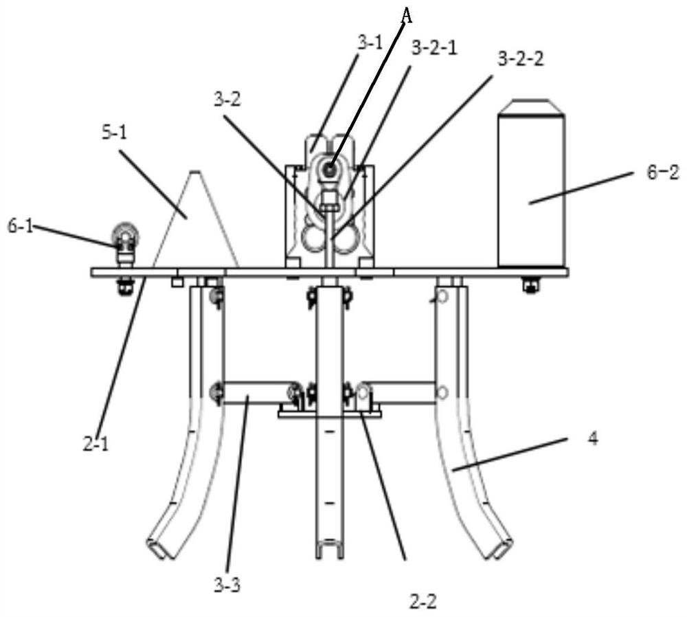
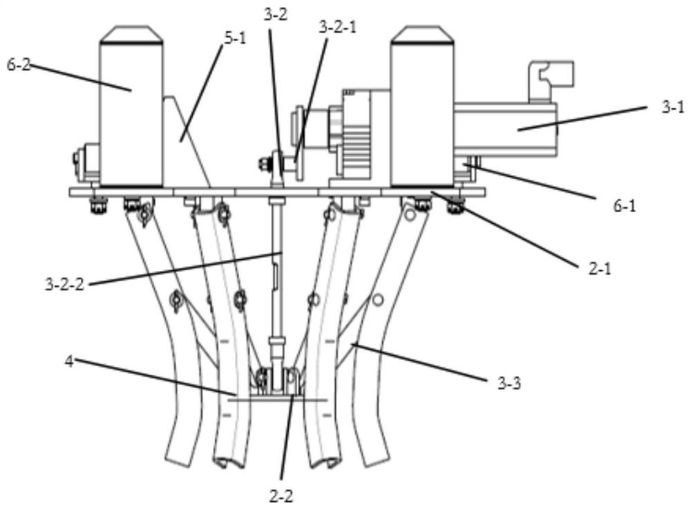
[0052] The above is one of the clamping devices in the tire conveying process provided by the present application, which can achieve clamping. Based on the above content, the present application can also provide another clamping mode (embodiment 2), For example: the clamping device can also be specifically: the clamping arm is a plurality of lifting rods; the driving mechanism includes: a clamping driver, a connecting rod, a drive sleeve, and a support rod; the mounting seat includes: a first assembly plate and a second assembly disk.

[0053] In this embodiment, the clamping driver and the lifting mechanism connecting seat are provided on the first assembly plate, and the lifting mechanism connecting seat is used for connecting the clamping device and the lifting mechanism, that is, : One end of the lifting belt is wound on the roller of the lifting mechanism, and the other end is fixed with the connecting seat; one end of the connecting rod is connected with one end of the c...


PUM


Abstract

The invention discloses a clamping device used in a tire conveying process. The clamping device comprises a clamping arm, an installing seat and a driving mechanism, wherein one end of the clamping arm is installed on the installing seat, and the other end of the clamping arm extends in the direction opposite to a tire; the clamping arm extends into the annular space inside the tire under the action of a conveying cart lifting mechanism and is opened in the direction near a toe mouth of the tire under the driving of the driving mechanism, and the clamping arm abuts against the toe mouth of thetire; the clamped tire can be moved to an appointed position along with a conveying cart; after the tire is in place, the clamping arm is closed in the direction away from the toe mouth under the driving of the driving mechanism; and under the action of the lifting mechanism, the clamping arm is contracted from the annular space of the tire and is separated from the tire. The clamping device is simple in structure, the manufacturing and conveying cost can be lowered, the clamping device is convenient to repair by workers, and the workpiece conveying efficiency is greatly improved.

Description

technical field [0001] The present application relates to the field of mechanical manufacturing, in particular to a clamping device in the tire conveying process. Background technique [0002] The EMS conveying system is mainly used to convey various equipment or parts in the workshop or between workshops, to realize a series of processes such as grinding, welding and assembling of workpieces conveyed between stations on the production line. Wide range of industry applications. [0003] Among them, the delivery of parts is particularly important, because the delivery of parts can improve the efficiency of the entire assembly line. For example, for the transportation of tires, the usual way is: [0004] 1. Roller bed conveying, put the tire on the roller bed, drive the tire on it to the designated position through the roller, and remove the tire from the roller bed manually. [0005] 2. Belt conveying, this kind of conveying method is similar to the above-mentioned roller b...

Claims


Application Information

Patent Timeline
Patent Type & Authority Patents(China)
IPC IPC(8): B65G47/90
CPCB65G47/901B65G2201/0273
Inventor 绳亮
Owner 湖北迪迈威智能装备有限公司
Learn More