
Sectional type air draft device used for laser cutting machine tool body

A laser cutting machine and ventilation device technology, applied in laser welding equipment, welding equipment, metal processing equipment, etc., can solve the problems of high production cost, low ventilation efficiency, difficult maintenance, etc., and achieve easy installation and maintenance, simple structure, and ventilation good effect

Pending Publication Date: 2018-03-02
WUHAN CARTER LASER ENG
View PDF0 Cites 1 Cited by
  • Summary
  • Abstract
  • Description
  • Claims
  • Application Information

AI Technical Summary

Problems solved by technology

Because the cutting position is constantly moving during laser cutting, its overall ventilation structure averages the ventilation force to each window, and the invalid ventilation area is large, so the ventilation efficiency is low and the energy consumption is high
[0004] At present, there are laser cutting machines on the market that use segmented ventilation devices with various structures. Generally, multi-zone single fan is used for ventilation. According to the position of the cutting head during laser cutting, the corresponding area is opened for ventilation, but the structure of the air duct switch is mostly rotary. Type damper, large turning stroke, poor sealing, complex structure, high production cost, and difficult to repair after failure

Method used


Image

  • Sectional type air draft device used for laser cutting machine tool body
  • Sectional type air draft device used for laser cutting machine tool body
  • Sectional type air draft device used for laser cutting machine tool body

Examples


Embodiment Construction

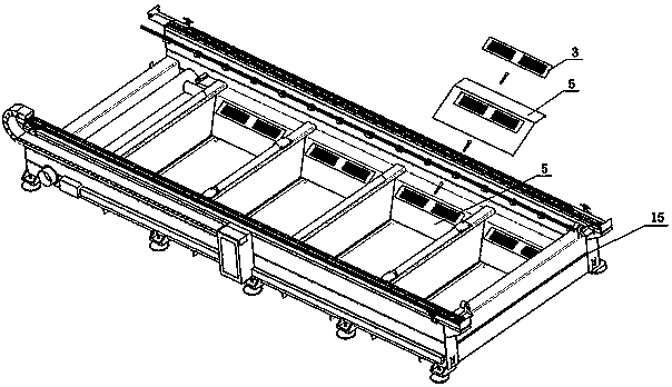
[0020] Such as figure 1 As shown, it is a structural schematic diagram of the segmented air exhaust device of the present invention installed on the laser cutting machine body. The segmented air exhaust device is fixed on the air exhaust panel 5 of the laser cutting machine body 15 by screws, and the exhaust air panel 5 is bent from sheet metal. The structure is fixed to the laser cutting machine body 15 by screws or welding, and is sealed and connected with the exhaust fan, so as to complete the extraction of the waste residue and exhaust gas formed in the cutting area of ​​the laser cutting machine body 15.

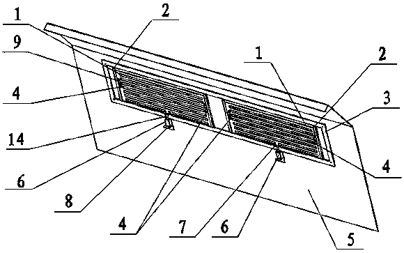
[0021] Such as figure 2 As shown, it is a schematic diagram of the overall structure of a segmented air exhaust device for a laser cutting machine body according to the present invention.

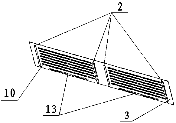
[0022] Such as image 3 As shown, it is a structural schematic diagram of the louver structure plate. The louver structure plate 3 is provided with a moving track 2, a louver air ...


PUM


Abstract

The invention discloses a sectional type air draft device used for a laser cutting machine tool body. The sectional type air draft device used for the laser cutting machine tool body comprises an adjusting plate, a shutter structural plate, an air draft panel, a small cylinder, a spring and the laser cutting machine tool body; the adjusting plate is provided with a spring installing hole position,a lifting platform, a cylindrical edge and corner and a square hole; the shutter structural plate is provided with a movement track, a shutter type gas inlet and an adjusting plate notch; the shutterstructural plate is fixed to the air draft panel of the laser cutting machine tool body through a screw; the adjusting plate is driven by the small cylinder and the spring to be capable of moving upand down along the movement track of the shutter structural plate; alignment and staggering of the shutter type gas inlet and the square hole are achieved; and opening and closing of an air draft gaspath are completed. According to the sectional type air draft device, an air draft device body corresponding to a cutting position can be opened during cutting of a laser tool bit, an unwanted air draft opening is closed, and therefore the sectional type air draft effect is achieved, energy waste can be effectively reduced, meanwhile, the overall structure is simple, and installing and maintainingare easy.

Description

technical field [0001] The invention belongs to the field of laser cutting, and in particular relates to a segmented ventilation device for a laser cutting machine body. Background technique [0002] As a new type of thermal cutting technology, laser cutting has the advantages of fast cutting speed, high production efficiency and small heat-affected zone. It has become one of the main cutting methods of metal sheets and has been widely used in the field of sheet metal processing. [0003] Existing laser cutting machines, especially high-power cutting machines, generate a large amount of waste gas due to high heat during cutting. If the cutting waste gas is not removed from the cutting area in time, the cutting waste gas will stay on the bed. If the cutting waste gas splashes When the machine tool needs precision protection, such as guide rails or flammable parts, it will affect the accuracy and service life of the machine tool and cutting head, so a simple ventilation device...

Claims


Application Information

Patent Timeline
IPC IPC(8): B23K26/38B23K26/70
CPCB23K26/38B23K26/702
Inventor 陈章陈华安陈伟黄新星薛建坤
Owner WUHAN CARTER LASER ENG
Learn More