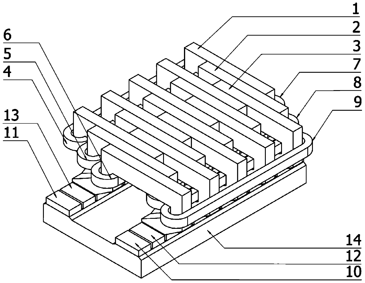
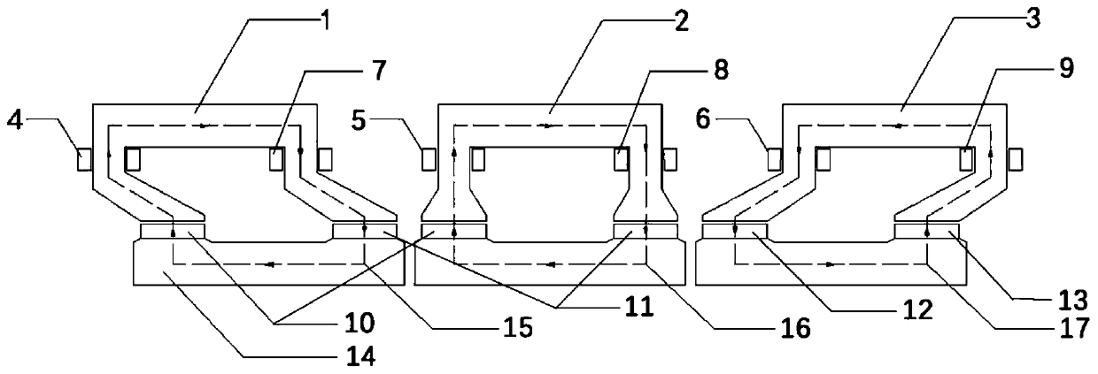
A flat-plate transverse flux permanent magnet synchronous linear generator
A linear generator and transverse magnetic flux technology, applied in magnetic circuits, electromechanical devices, electrical components, etc., can solve the problems of large cogging force and low space utilization, and achieve small cogging force, simple magnetic circuit and high efficiency. The effect of space utilization and power density
- Summary
- Abstract
- Description
- Claims
- Application Information
AI Technical Summary
Problems solved by technology
Method used
Image
Examples
Embodiment 1
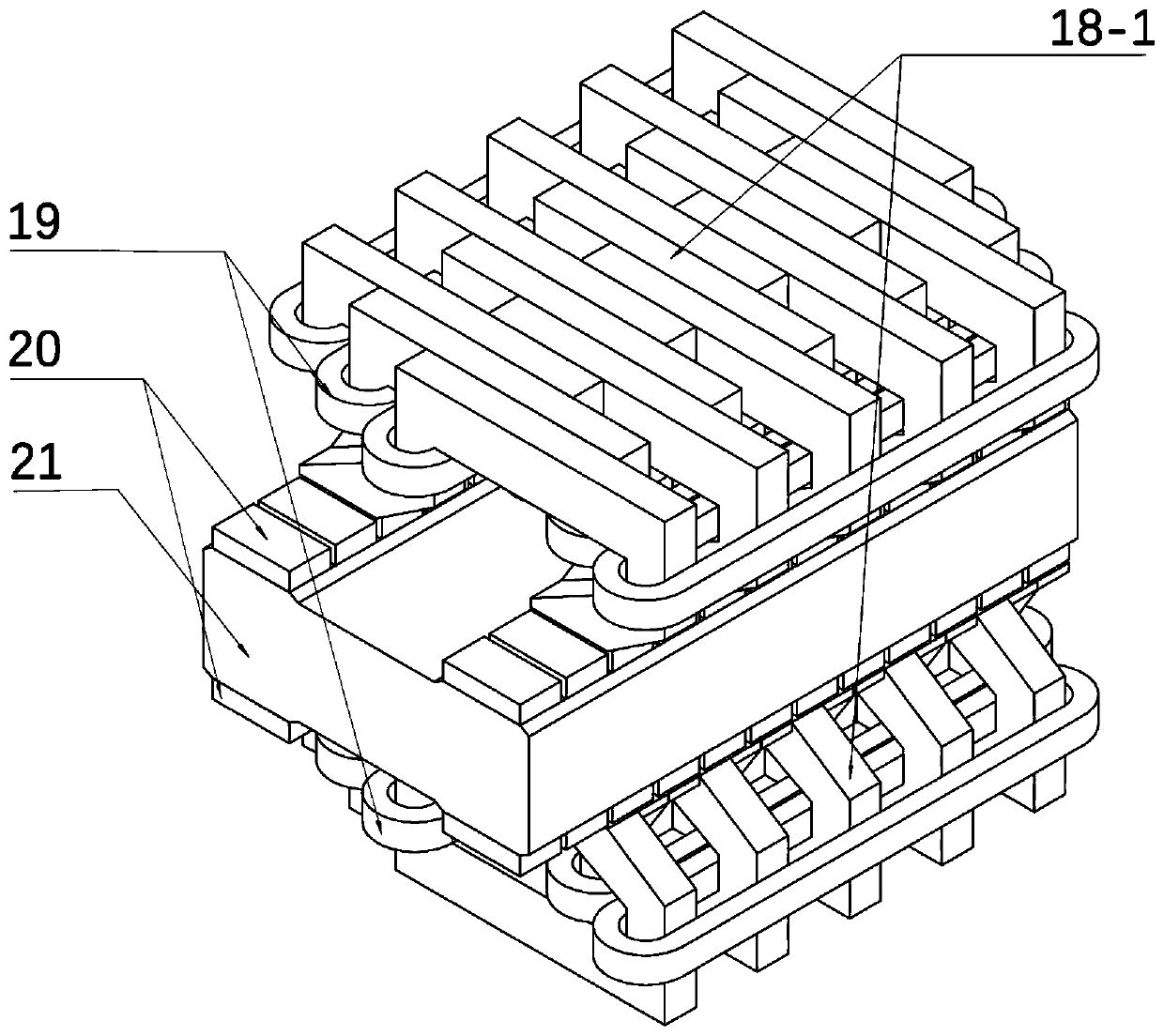
[0030] image 3 Shown is Embodiment 1 of the present invention that can be used in a bilateral transverse flux permanent magnet synchronous linear generator: a bilateral transverse flux permanent magnet synchronous linear generator. Two sets of transverse magnetic flux permanent magnet synchronous linear generator primary 18 mirror symmetrically placed. Two sets of racetrack-shaped windings 19 are wound on the primary tooth poles of the linear generator, secondary magnets 20 are evenly arranged on both sides of the secondary iron core 21, and the directions of magnetization between adjacent magnets are opposite. When the secondary moves at a certain speed, the flux linkage between the coils changes according to the sinusoidal law, thereby generating electric energy.
Embodiment 2
[0032] The transverse magnetic flux permanent magnet synchronous linear generator of the present invention can be used in a double-float floating direct-drive point-absorption wave energy power generation system. Figure 4 Shown is Embodiment 2: a double-float floating direct-drive point-absorption wave energy power generation system. Such as Figure 4 As shown, the double-floating floating direct-drive point-absorbing wave energy generation system floats on the sea as a whole, and the double-floating buoys 22 float on the sea. The out-of-phase primary iron core 18 of the transverse flux permanent magnet synchronous generator of the present invention is installed inside the floating buoy 22, the winding 19 is wound around the tooth pole body of the three-phase primary iron core, the surface of the magnetic steel 20 is attached to the surface of the secondary iron core 21, and the secondary The iron core 21 is connected to the damping float 24 through the connecting rod 23 . ...
Embodiment 3
[0035] The transverse flux permanent magnet synchronous linear generator of the present invention can be used in a direct-drive wave energy power generation system fixed on the seabed. Figure 5 Shown is Embodiment 3: a direct-drive point-absorption wave energy power generation system with the bottom fixed on the seabed. Such as Figure 5 As shown, the motor sealing casing 29 is fixed on the sea bed of the seabed, and the floating buoy 28 floats on the sea surface. The out-of-phase primary iron core 18 of the linear generator of the present invention is integrally fixed on the inner side of the motor casing 29 . The primary winding 19 is wound around the tooth pole body of the three-phase primary iron core, and the surface of the magnetic steel 20 is attached to the surface of the secondary iron core 21. Floats 28 are connected. After the secondary moves upwards, the return spring 30 can restore the secondary to its initial position. The top of the casing 29 is provided wi...
PUM
 Abstract
Description
Claims
Application Information
 - R&D
- Intellectual Property
- Life Sciences
- Materials
- Tech Scout
- Unparalleled Data Quality
- Higher Quality Content
- 60% Fewer Hallucinations
Browse by: Latest US Patents, China's latest patents, Technical Efficacy Thesaurus, Application Domain, Technology Topic, Popular Technical Reports.
© 2025 PatSnap. All rights reserved.Legal|Privacy policy|Modern Slavery Act Transparency Statement|Sitemap|About US| Contact US: help@patsnap.com


