
On-line cutter

A cutting knife and static technology, which is applied in the direction of shearing devices, knives for shearing machine devices, shearing machine equipment, etc., can solve the problems of complex structure, poor precision, and many parts, so as to achieve accurate and reliable positioning and prevent displacement deviation Effect

Pending Publication Date: 2018-02-27
江苏凌云恒晋汽车零部件有限公司
View PDF1 Cites 2 Cited by
  • Summary
  • Abstract
  • Description
  • Claims
  • Application Information

AI Technical Summary

Problems solved by technology

The cutter mechanism using the above mechanism has a complicated structure and many parts, and requires multiple parts to be used together, and the precision is poor

Method used


Image

  • On-line cutter
  • On-line cutter
  • On-line cutter

Examples


Embodiment Construction

[0025] The present invention is further described in conjunction with the accompanying drawings and examples.

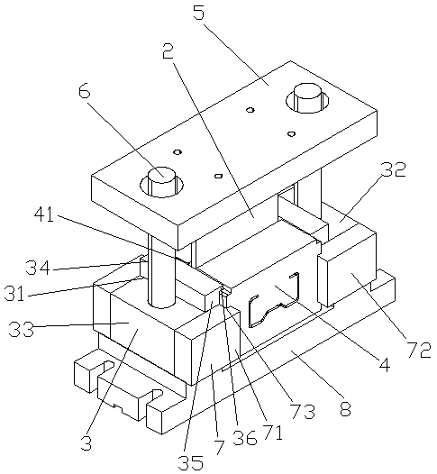
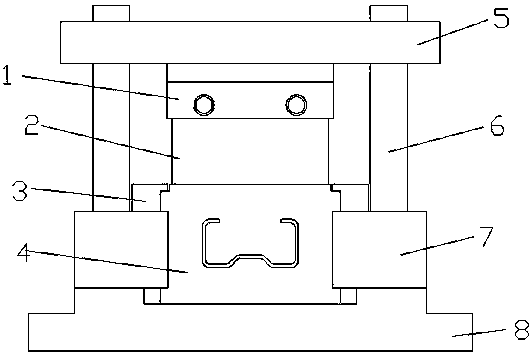
[0026] Such as Figure 1-7 Shown, a kind of online cutter comprises upper template 5, lower template 8, dynamic cutter 2, static cutter 4, lower template 8, static cutter 4 is set on lower template 8, and static cutter 4 is set in static The fixed guide plate 3 and baffle plate 7 on both sides of the cutter 4 are positioned, the dynamic cutter 2 is set above the static cutter 4, the dynamic cutter 2 is set at the bottom of the upper template 5, and the two ends of the upper template 5 are respectively set on two guide pillars 6, the lower ends of the two guide pillars 6 are correspondingly arranged on the fixed guide plate 3.

[0027] The lower template 8 includes a bottom plate 81, and a first protrusion 82 and a second protrusion 83 provided on the bottom plate 81. The first protrusion 82 and the second protrusion 83 are sequentially arranged along the width dire...


PUM


Abstract

The invention relates to a cutter, in particular to an on-line cutter, and belongs to the technical field of cutting-off devices. The on-line cutter comprises an upper template (5), a lower template (8), a dynamic cutter body (2) and a static cutter body (4). The static cutter body (4) is arranged on the lower template (8), the static cutter body (4) is positioned through a fixed guiding plate (3)and a baffle (7) arranged on the two sides of the static cutter body (4), and the dynamic cutter body (2) is arranged above the static cutter body (4); and the dynamic cutter body (2) is arranged atthe bottom of the upper template (5), the two ends of the upper template (5) arranged on two guiding columns (6) in a penetrating and sleeving mode correspondingly, and the lower ends of the two guiding columns (6) are correspondingly arranged on the fixed guiding plate (3). According to the on-line cutter, positioning is accurate, the dynamic cutter body and the static cutter body are arranged upand down, the dynamic cutter body is driven by hydraulic equipment, the cutting-off quality is good, and the efficiency is high.

Description

technical field [0001] The invention relates to a cutter, in particular to an online cutter, and belongs to the technical field of cutting devices. Background technique [0002] A cutter is a tool used for cutting. GB / T1008-2008 "Basic Terms of Machining Technology Equipment" defines it as a type of single-edged tool used for turning, boring, slotting, and planing. The Chinese invention patent application with the publication number CN 104354937 A and the publication date of February 18, 2015 discloses a cutter mechanism, which is located on the mounting frame body. , driving components, fixed cutters and movable cutters that can move open and close each other. The fixed cutter is fixed on the mounting frame body, and one end of the movable cutter extends along the opening and closing direction to a stacking guide part that overlaps with the fixed cutter, and the stacking guide The leading part, the end of the movable cutter adjacent to the fixed cutter and the fixed cutte...

Claims


Application Information

Patent Timeline
Patent Type & Authority Applications(China)
IPC IPC(8): B23D15/04B23D35/00
CPCB23D15/04B23D35/001
Inventor 金文海基军侯敏赵云王丽娟丁家东
Owner 江苏凌云恒晋汽车零部件有限公司
Learn More