
Fuel gas supply system

A gas supply system and gas technology, applied in the direction of charging system, oil supply device, combustion engine, etc., can solve the problems of reduced reliquefaction efficiency of evaporated gas, influence of application and treatment of evaporated gas, and reduction of gas calorific value, etc., to achieve improved Reliquefaction efficiency, simple structure, and improved energy efficiency

Active Publication Date: 2018-02-23
SAMSUNG HEAVY IND CO LTD
View PDF5 Cites 0 Cited by
  • Summary
  • Abstract
  • Description
  • Claims
  • Application Information

AI Technical Summary

Problems solved by technology

[0007] Therefore, the boil-off gas produced by the natural vaporization inside the storage tank contains more components of nitrogen with a relatively low boiling point, which leads to a decrease in the reliquefaction efficiency of the boil-off gas, and has an impact on the application and treatment of the boil-off gas
[0008] In addition, when the boil-off gas is supplied to the ship engine as fuel gas, the nitrogen contained in the boil-off gas will affect the calorific value of the gas

Method used


Image

  • Fuel gas supply system
  • Fuel gas supply system

Examples


Embodiment Construction

[0029] Embodiments of the present invention will be described in detail below with reference to the accompanying drawings. The following embodiments are provided in order to fully convey the technical idea of ​​the present invention to those having general knowledge in the technical field to which the present invention pertains. The present invention is not limited to the examples provided below, and it can also be embodied in other forms. In the drawings, illustrations of parts irrelevant to the description are omitted in order to clarify the present invention, and components are shown slightly exaggerated to facilitate understanding.

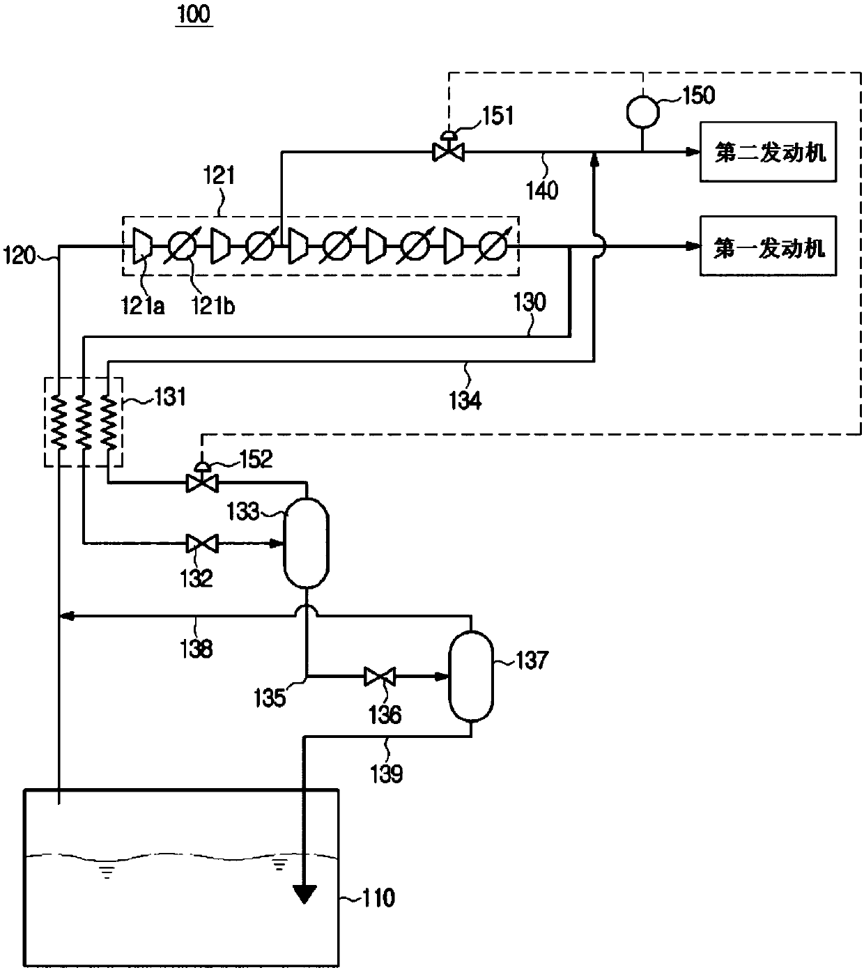
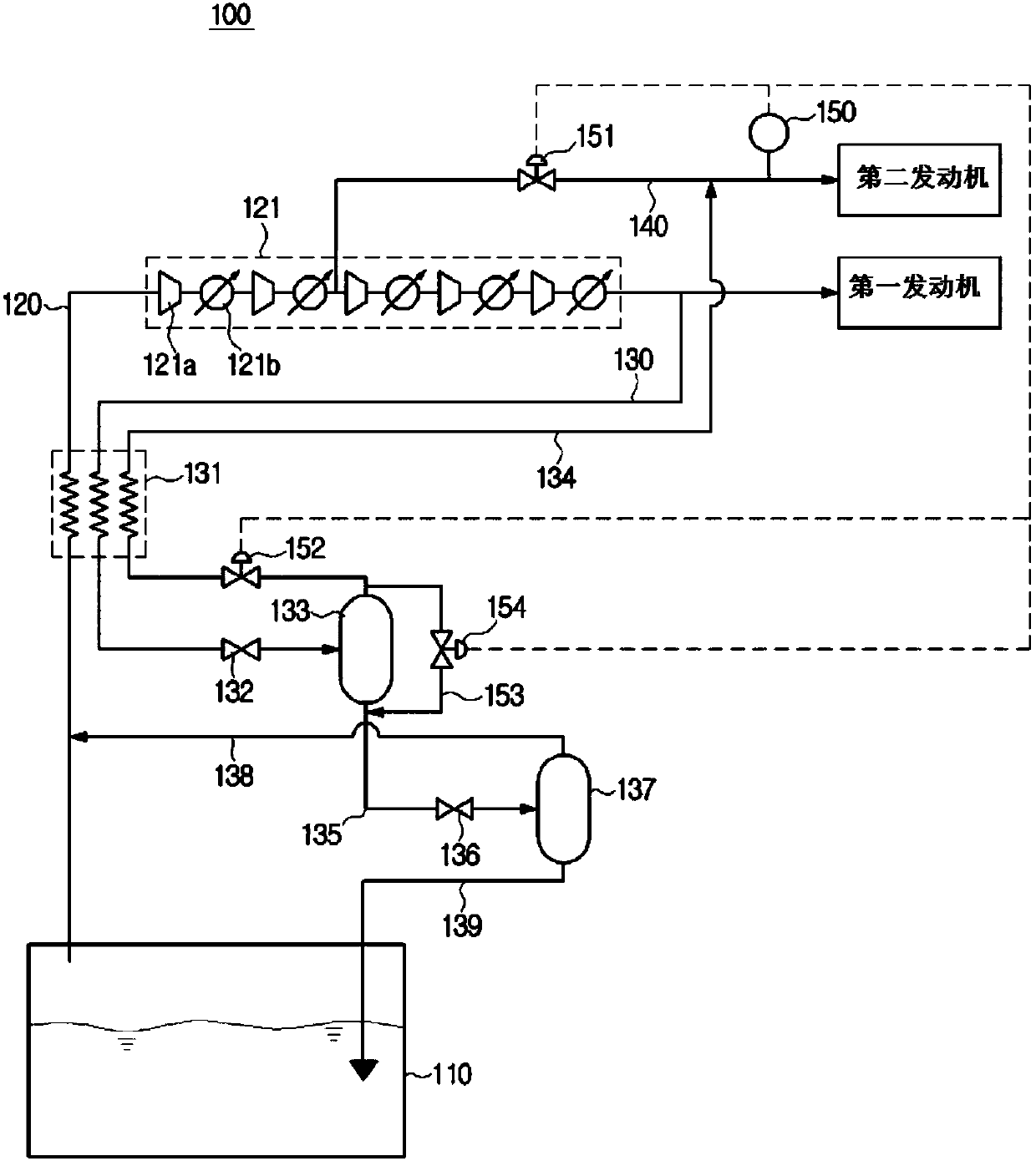
[0030] figure 1 A gas supply system 100 related to an embodiment of the present invention is shown.

[0031] refer to figure 1 , The gas supply system 100 related to the embodiment of the present invention includes: a storage tank 110; a compression part 121 for pressurizing the boil-off gas in the storage tank 110, and the boil-off gas pre...


PUM


Abstract

Disclosed is a fuel gas supply system. A fuel gas supply system, according to an embodiment of the present invention, comprises: a storage tank that stores a liquefied gas and a boil-off gas; a firstfuel gas supply line that is provided with a compression unit for compressing the boil-off gas of the storage tank, and supplies, to a first engine, the boil-off gas that is compressed while passing through the compression unit; a second fuel gas supply line that branches from the middle of the compression unit and supplies, to a second engine, the boil-off gas that is partially compressed by thecompression unit; a re-liquefaction line that receives a part of the compressed boil-off gas and re-liquefies the same; and a heating-value adjustment unit that measures and adjusts the heating valueof the fuel gas that is supplied to the second engine, wherein the re-liquefaction line includes: a cooling unit that cools the compressed boil-off gas; a first expansion valve that primarily reducesthe pressure of the compressed boil-off gas having passed through the cooling unit; a first gas-liquid separator that separates the boil-off gas in a gas-liquid mixture state that has passed through the first expansion valve into a gaseous component and a liquid component; a boil-off gas circulation line that supplies the gaseous component separated by the first gas-liquid separator to the secondengine; and a liquefied-gas circulation line that receives the liquid component separated by the first gas-liquid separator.

Description

technical field [0001] The invention relates to gas supply systems. Background technique [0002] With the strengthening of the International Maritime Organization (IMO) regulation on the emission of greenhouse gases and various air pollutants, in the shipbuilding and shipping industries, the use of clean energy natural gas to replace conventional fuels such as heavy oil and diesel for ship gas has increased. [0003] In order to facilitate storage and transportation, natural gas (Natural Gas) is usually cooled to -162 degrees Celsius, its volume is compressed to 1 / 600, and it is managed and applied in the form of colorless and transparent ultra-low temperature liquefied natural gas (Liquefied Natural Gas). [0004] This liquefied natural gas is stored and transported in insulated storage tanks on the ship's hull. However, in actual operation, it is impossible to completely insulate LNG for transportation, and the external heat will continue to be conducted to the inside of...

Claims


Application Information

Patent Timeline
IPC IPC(8): F02M21/02
CPCF02M21/0287B63B25/16F02M21/02F02M25/08F17C5/02F17C7/04F02B73/00F25J1/0025F25J1/004F25J1/0202F25J1/023F25J1/0244F25J1/0277F25J2220/62Y02T10/30
Inventor 李元斗姜镐淑朴秀律李钟哲李孝垠韩俊熙黄霓琳尹虎炳
Owner SAMSUNG HEAVY IND CO LTD
Learn More