Coulomb-force-traction spherical compression jet airflow arc-extinguishing device and sphere type arcing horn

A technology of jet air flow and arc extinguishing device, which is applied to corona discharge devices, electrical components, insulators, etc., can solve the problem of not being able to ensure the safe operation of metal transmission lines, and achieve safe and stable operation, good lightning protection and arc extinguishing. Effect

Active Publication Date: 2018-02-23
王巨丰
View PDF3 Cites 7 Cited by
  • Summary
  • Abstract
  • Description
  • Claims
  • Application Information

AI Technical Summary

Problems solved by technology

The above-mentioned lines where lightning tripping accidents occurred have been erected with lightning protection lines and adopted various conventional lightning protection technical measures. It can be seen that the existing various lightning protection technical measures cannot guarantee the safe operation of metal transmission lines.

Method used


Image

  • Coulomb-force-traction spherical compression jet airflow arc-extinguishing device and sphere type arcing horn
  • Coulomb-force-traction spherical compression jet airflow arc-extinguishing device and sphere type arcing horn
  • Coulomb-force-traction spherical compression jet airflow arc-extinguishing device and sphere type arcing horn

Examples


Embodiment 1

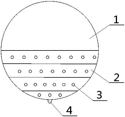
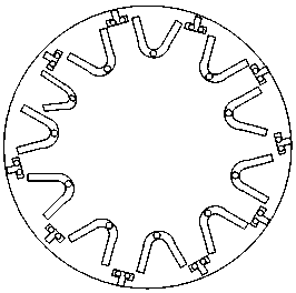
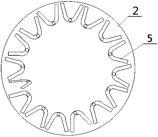
[0043] Such as Figure 1-4 As shown, a spherical compressed jet air arc extinguishing device pulled by Coulomb force is mainly composed of upper and lower hemispheres, wherein the upper hemisphere is a metal hemisphere 1 for Coulomb force arc ignition, and the lower hemisphere is an insulating compressed arc extinguishing hemisphere 2; The insulating compression arc extinguishing hemisphere 2 is provided with several layers of arc extinguishing channels arranged along the circumference, and several arc extinguishing tubes are placed in each layer of arc extinguishing channels, and the last arc extinguishing channel in the upper layer of arc extinguishing channels The tube is electrically connected to the first arc extinguishing tube in the arc extinguishing channel of the next layer, and the ends of two adjacent arc extinguishing tubes in the same layer of arc extinguishing channel are connected through the connecting piece 6; The joints of two adjacent arc extinguishing tubes...

Embodiment 2

[0047] The difference between this embodiment and embodiment 1 is: as Figure 7 , Figure 8 As shown, the arc extinguishing tube adopts an in-line arc extinguishing tube; and the ends of two adjacent in-line arc extinguishing tubes away from the outer surface of the insulating compression arc extinguishing hemisphere are connected together through the arc connecting electrodes; The two ends of the arc-guiding connection electrode are respectively embedded in the in-line arc extinguishing tube. The inside of the in-line arc extinguishing tube is provided with an arc guiding ball and two compression cold wall tubes; the arc guiding ball is placed between the two compression cold wall tubes, There is also an arc guide ring at the port.

Embodiment 3

[0049] The difference between this embodiment and embodiment 1 is: as Image 6 As shown, the outer surface of the insulating compression arc extinguishing hemisphere 2 is also provided with a skirt 10, and the skirt 10 is arranged along the direction in which the airflow outlets 3 are arranged.


PUM


Abstract

The invention discloses a Coulomb-force-traction spherical compression jet airflow arc-extinguishing device and a sphere type arcing horn. The Coulomb-force-traction spherical compression jet airflowarc-extinguishing device is mainly composed of upper and lower hemispheres, wherein the upper hemisphere is a Coulomb-force arc-striking metal hemisphere, and the lower hemisphere is an insulated compression arc-extinguishing hemisphere; multiple layers of arc-extinguishing channels arranged along the circumference are formed in the insulated compression arc-extinguishing hemisphere; and the bottom part of the insulated compression arc-extinguishing hemisphere is provided with an arc-striking electrode. The Coulomb-force-traction spherical compression jet airflow arc-extinguishing device and the sphere type arcing horn are simple in structure and can induce lightning to be conducted firstly, so that the power transmission metal line lightning shielding failure accident caused by lightninginterception failure can be reduced; and a thunder current is compressed, lengthened, thinned and ejected to extinguish arc, so that back striking probability caused by lightning stroke of a lightningconductor can be lowered.

Description

technical field [0001] The invention relates to a lightning protection and arc extinguishing device, in particular to a spherical compressed jet airflow arc extinguishing device and a spherical arc striking angle drawn by Coulomb force. Background technique [0002] At present, in order to protect the conductors of metal transmission lines from being struck by lightning, it is generally used to erect lightning conductors. my country's electric power industry standard DL / T620-1997 "Overvoltage Protection and Insulation Coordination of AC Electrical Installations" stipulates in Article 6.1.2: 110kV along Lightning protection lines should be erected along the entire line. In mountainous areas and areas with particularly strong lightning activities, it is advisable to erect lightning protection lines along the entire line. The structure of the lightning protection line is to install a bare steel strand on the top of the left and right transmission towers above the three-phase tra...

Claims


Application Information

Patent Timeline
IPC IPC(8): H01T19/00H01T1/02H01T1/10H01B17/46H01B17/48
CPCH01T1/02H01T1/10H01T19/00H01B17/46H01B17/48
Inventor 李籽剑夏志坚周鑫黄上师闫坤王硕覃安杰余杰皓王中黄嘉曦王嬿蕾郑传啸毕洁廷孔佳琦周勇军韩力
Owner 王巨丰
Why Eureka
Try Eureka