Autonomous driving system and autonomous driving vehicle
A technology for autonomous driving and vehicles, applied in motor vehicles, collision avoidance systems, traffic control systems, etc., to solve problems such as traffic imbalance and obstruction of traffic
- Summary
- Abstract
- Description
- Claims
- Application Information
AI Technical Summary
Problems solved by technology
Method used
Image
Examples
Embodiment approach 1
[0148] [Hardware Configuration of Embodiment 1]
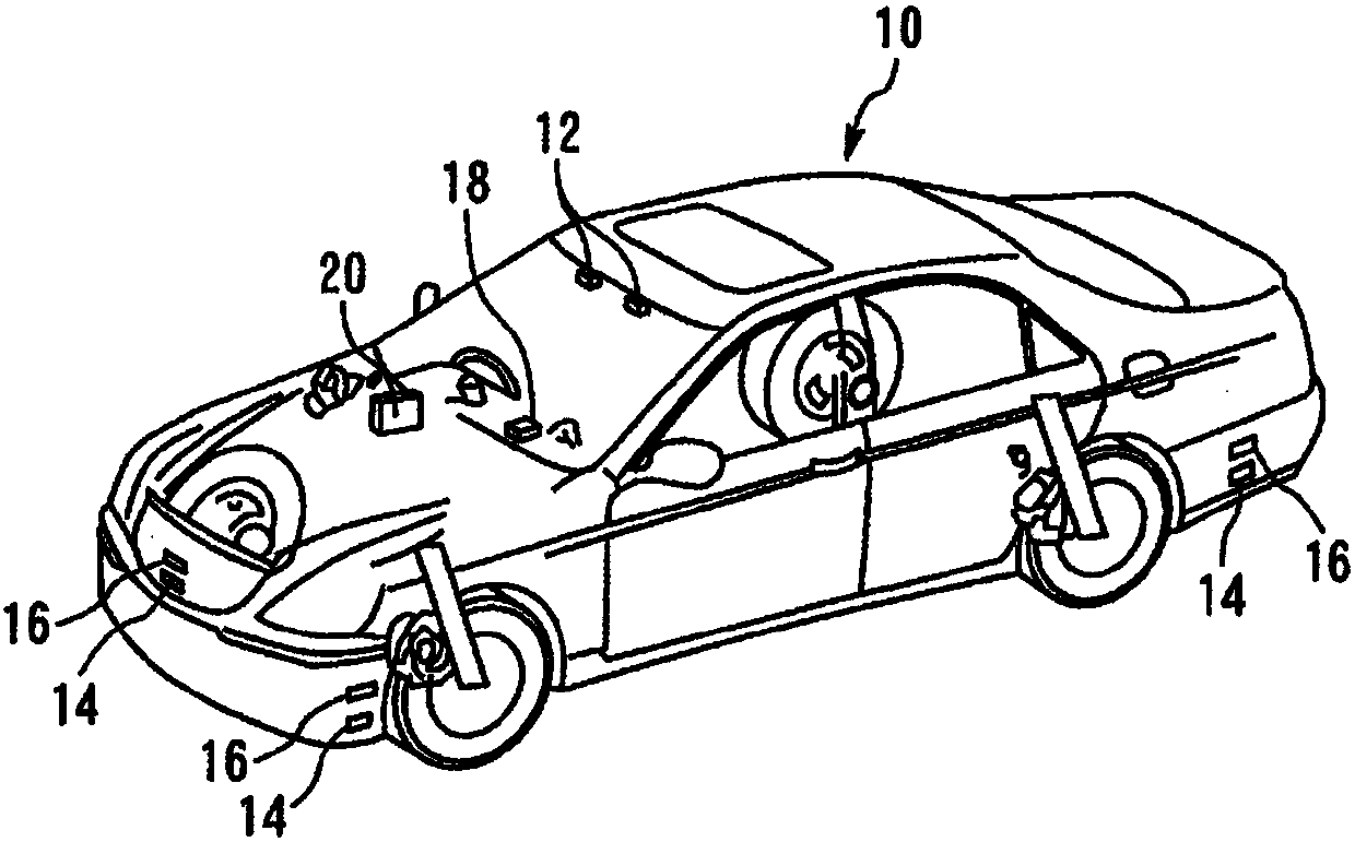
[0149] figure 1 It is a figure which shows the hardware structure of the autonomous vehicle 10 which concerns on Embodiment 1 of this invention. Such as figure 1 As shown, a stereo camera 12 is mounted on a vehicle 10 . The stereo camera 12 can stereoscopically photograph the front of the vehicle 10 from a predetermined angle of view. In addition, the stereo camera 12 may be replaced with a monocular camera.
[0150] In addition, a plurality of LIDAR (Laser Imaging Detection and Ranging, ie, laser radar) units 14 are mounted on the vehicle 10 so as to surround the vehicle. More specifically, a total of six LIDAR units 14 are mounted, and the front of the vehicle, the left and right front of the vehicle, the rear of the vehicle, and the left and right rear of the vehicle are the detection areas. With the LIDAR unit 14, the outline of an object present in each detection area and the distance to the object can be detected. ...
Embodiment approach 2
[0187] Next, refer to Figure 6 Embodiment 2 of the present invention will be described. The self-driving vehicle 10 of the present embodiment has the same hardware configuration as that of the first embodiment. In this embodiment, the ECU20 can execute Figure 6 The flow shown is realized by performing the lane determination processing without performing the above-mentioned Figure 5 process shown.
[0188] and Figure 5 In the same flow shown, the ECU 20 starts from recognizing the lane reselection instruction Figure 6 The flow shown (step 44). Below, for Figure 6 neutralize Figure 5 Steps that are the same as or correspond to the illustrated steps are given common symbols, and descriptions thereof are omitted or simplified.
[0189] Figure 6 After the flow shown starts, firstly, a driving lane is tentatively determined (step 62). Here, the driving lane is tentatively determined based on the recognition result of the surrounding objects and the recognition resu...
Embodiment approach 3
[0195] Next, refer to Figure 7 and Figure 8 Embodiment 3 of the present invention will be described. The self-driving vehicle 10 of the present embodiment has the same hardware configuration as that of the first embodiment. This embodiment has the following characteristics, that is, the automatic driving vehicle 10 determines the distribution target of the vehicle in combination with the driving route, and makes the standard driving lane dispersive so as to achieve the distribution target.
[0196] Figure 7 It is a block diagram showing the characteristic part of ECU20 in this embodiment. Below, for Figure 7 neutralize Figure 4 Elements that are the same as or correspond to the elements shown are given common symbols, and descriptions thereof are omitted or simplified.
[0197] In the present embodiment, the lane selection unit 38 includes a travel lane specifying unit and a distribution target specifying unit 74 . The driving lane specifying unit 72 executes the d...
PUM
 Abstract
Description
Claims
Application Information
 - R&D
- Intellectual Property
- Life Sciences
- Materials
- Tech Scout
- Unparalleled Data Quality
- Higher Quality Content
- 60% Fewer Hallucinations
Browse by: Latest US Patents, China's latest patents, Technical Efficacy Thesaurus, Application Domain, Technology Topic, Popular Technical Reports.
© 2025 PatSnap. All rights reserved.Legal|Privacy policy|Modern Slavery Act Transparency Statement|Sitemap|About US| Contact US: help@patsnap.com


