Rotating obstacle clearing drill bit

A drill bit and obstacle removal technology, which is applied in the direction of pipes/pipe joints/fittings, special pipes, mechanical equipment, etc. It can solve the problems of difficult to clean blockages and waste blockages in drainage pipes, etc.

Active Publication Date: 2018-02-23
郑州中原科技工程研究院有限公司
View PDF4 Cites 1 Cited by
  • Summary
  • Abstract
  • Description
  • Claims
  • Application Information

AI Technical Summary

Problems solved by technology

[0007] The technical problem to be solved by the present invention is to provide a rotary obstacle-clearing drill bit, which solves the difficulty of cleaning the garbage blockages in the drainage pipes in the prior art, especially when it is made of soft It is difficult to clean up the clogging of solid waste and hard waste mixed together

Method used


Image

  • Rotating obstacle clearing drill bit
  • Rotating obstacle clearing drill bit
  • Rotating obstacle clearing drill bit

Examples


Embodiment 1

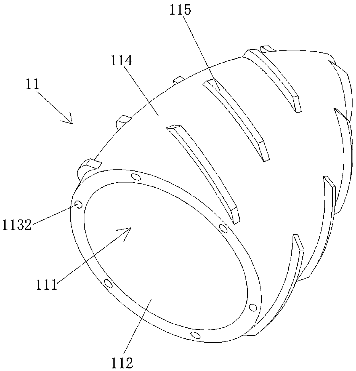
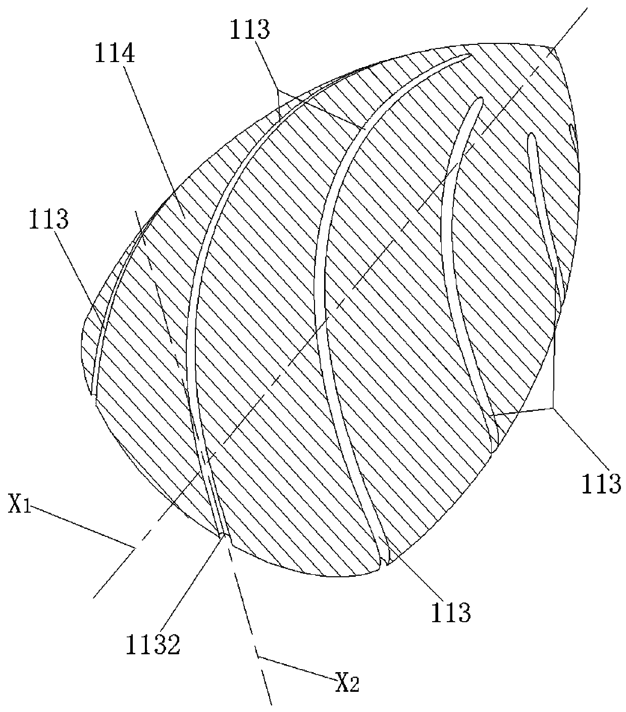
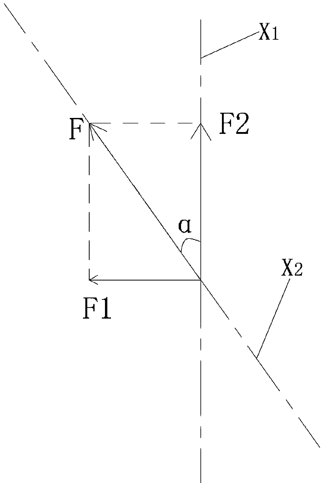
[0035] Please also refer to Figure 1 to Figure 7 , figure 1 It is a perspective view of Embodiment 1 of the rotary obstacle-clearing drill bit of the present invention, figure 2 for figure 1 Schematic diagram of the spiral channel in the cavity wall of the middle bit body, image 3 for figure 1 Schematic diagram of the reaction force of the high-pressure water sprayed from the spiral channel of the middle rotary obstacle-clearing drill bit on the rotary obstacle-clearing drill bit, Figure 4 for figure 1 Rear view of the Rotary Wrecker Bit in the middle, Figure 5 for figure 1 Side view of the Rotary Wrecker Bit in the middle, Image 6 for figure 1 Front view of the Rotary Wrecker Bit in the middle, Figure 7 for figure 1 Schematic diagram of the structure of the blade of the rotary obstacle-clearing drill bit.

[0036] The rotary obstacle removal drill bit of the present invention includes a drill body 11. A high-pressure water containing cavity 111 is arranged i...

Embodiment 2

[0051] Please also refer to Figure 8 to Figure 10 , Figure 8 It is a perspective view of Embodiment 2 of the rotary obstacle-clearing drill bit of the present invention, Figure 9 for Figure 8 Rear view of the Rotary Wrecker Bit in the middle, Figure 10 for Figure 8 A cross-sectional view of the connection between the middle rotary obstacle removal drill bit and the joint at the front end of the high-pressure water pipe. The afterbody of drill body 21 is provided with the water pipe joint 22 that is used for freely rotating sealing connection with the high-pressure water pipe of the pipeline wrecker. A water injection port for injecting high-pressure water in the body 211. The rotary wrecker drill bit will also be able to rotate freely while being sealed with the high-pressure water pipe of the pipeline wrecker. The water pipe joint 22 is set to make the connection more convenient. The high-pressure water pipe of the water pipe joint 22 and the pipeline wrecker can b...


PUM


Abstract

The invention discloses a rotating obstacle clearing drill bit. The rotating obstacle clearing drill bit comprises a drill bit body, a high-pressure water containing cavity is formed in the drill bitbody, multiple spiral water channels which are communicated in a cut-through mode along the cavity wall from top to bottom are arranged in the cavity wall of the high-pressure water containing cavity,and each spiral water channel comprises a water inlet and a water outlet, so that high-pressure water in the high-pressure water containing cavity enters the corresponding spiral water channels through the water inlets and flows out of the water outlets to exert forward driving force and rotating turning force to the rotating obstacle clearing drill bit. By arranging the spiral water channels, the rotating obstacle clearing drill bit rotatably advances at a high speed in a water drainage pipeline, and then the water drainage pipeline blocked by waste blockages can be dredged; and by arrangingblades used for cutting and crushing the blockages in the water drainage pipeline on the outer surface of the drill bit body, the rotating obstacle clearing drill bit has the high crushing capabilityon large soft waste blockages and hard waste blockages in the water drainage pipeline and can smoothly dredge the water drainage pipeline for the water drainage pipeline difficult to dredge.

Description

technical field [0001] The invention relates to the technical field of pipeline obstacle removal devices, in particular to a rotary obstacle removal drill bit. Background technique [0002] With the development of urban construction in the direction of modernization, the construction and maintenance of urban drainage facilities also need to keep up with the pace of urban development and growth. Drainage facilities are an important guarantee for the normal operation of cities. The smooth flow of drainage facilities can ensure that the urban environment is clean and hygienic, and residents healthy lifestyle. [0003] At present, due to the aging of facilities and insufficient supervision, the drainage pipes in many cities are seriously clogged, which directly affects the drainage capacity of the drainage pipes. In the rainy season, it may even form waterlogging. People's traffic trips will cause residential houses to be flooded more seriously, which will cause huge economic l...

Claims


Application Information

Patent Timeline
Patent Type & Authority Applications(China)
IPC IPC(8): F16L55/38F16L55/40F16L101/12
CPCF16L55/38F16L55/40F16L2101/12Y02P70/10
Inventor 吴彦云扶涛涛闫卫洲王守宪
Owner 郑州中原科技工程研究院有限公司
Why Eureka
Try Eureka