
A composite anchorage of suspension bridge tunnel anchor and its construction method

A tunnel anchor and combined technology, applied in bridge construction, construction, bridges, etc., can solve the problems of the durability of the composite anchorage cable being difficult to ensure, the overall stability requirements are high, and the difficulty of forming a hole in a large chamber. , to achieve the effect of reducing the amount of excavation and the amount of concrete used, the construction progress is fast, and the construction process is less.

Active Publication Date: 2022-05-03
CHANGJIANG RIVER SCI RES INST CHANGJIANG WATER RESOURCES COMMISSION
View PDF18 Cites 0 Cited by
  • Summary
  • Abstract
  • Description
  • Claims
  • Application Information

AI Technical Summary

Problems solved by technology

It is difficult to guarantee the durability of the composite anchor cable of gravity anchor (tunnel anchor) + anchor cable
There are many drilling holes for the composite anchorage of rock mass and reinforced concrete slab, and the construction process is complicated
With the in-depth understanding of the mechanism of tunnel anchoring, the surrounding rock of the tunnel anchor is sufficient to withstand the pulling force of the main cable, and can be used as the main stress structure of the main cable of the suspension bridge. However, since the longitudinal section of the tunnel anchor is the deformation section of the city gate, the section of the tunnel mouth is small, and the section of the anchor plug body is large, so the requirements for the overall stability of the terrain and rock mass are high, so the tunnel anchor Generally, it can only be used in mountainous areas, where the overall stability of the rock mass is good, and it is not easy to collapse during the construction process. It cannot be used for some rock and soil masses with low engineering quality, and due to the large cross-section of the tunnel anchor, there are still large holes. chamber hole problem

Method used


Image

  • A composite anchorage of suspension bridge tunnel anchor and its construction method
  • A composite anchorage of suspension bridge tunnel anchor and its construction method
  • A composite anchorage of suspension bridge tunnel anchor and its construction method

Examples


Embodiment

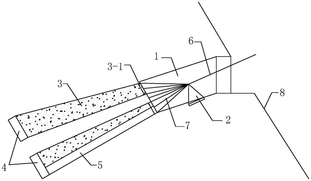
[0027] Embodiment: A construction method of a suspension bridge tunnel anchor combined anchorage, characterized in that the specific steps are as follows:

[0028] (1) Excavate the front anchor chamber 1 on the side of the mountain slope on one side or both sides of the suspension bridge, support or reinforce the cave wall and opening of the front anchor chamber, line the cave wall and bottom plate, and pour concrete on the front anchor surface; The front anchor chamber 1 is in the shape of a city gate with an inclination angle of 18°;

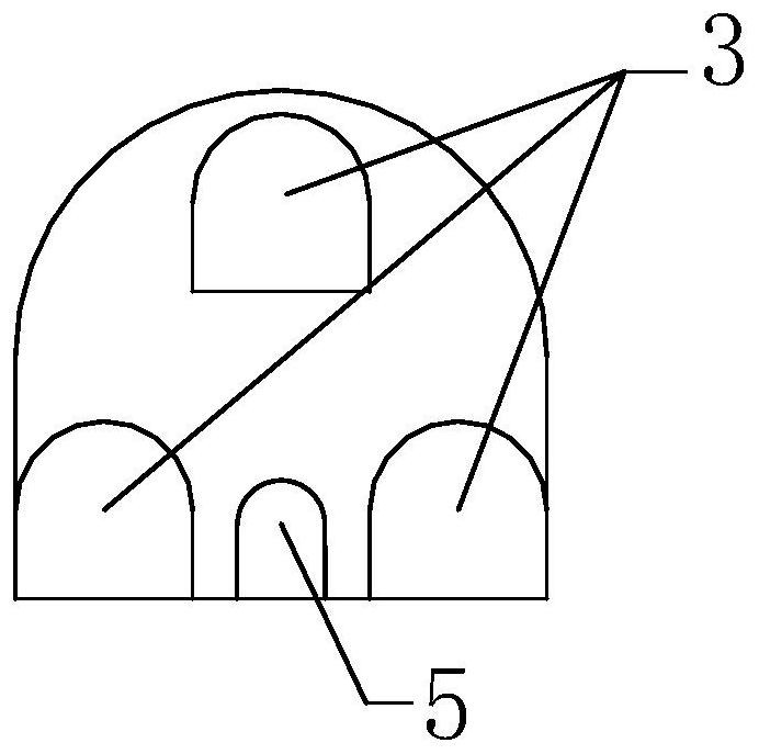
[0029] (2) According to the measurement, it is determined that the tension of the main cable of the suspension bridge to be constructed is 1.2×10 5 kN, anchorage and surrounding rock engineering quality grades are mostly grade III and some are grade IV. Three small-section tunnel anchorages are designed, and the front section height and bottom edge width of each small-section tunnel anchorage are respectively 3m. The height of the rear sectio...


PUM


Abstract

The invention provides a suspension bridge tunnel anchor composite anchorage and a construction method. The combined anchorage is to excavate the front anchor chamber on one or both sides of the suspension bridge, and then divide it into multiple small-section tunnel anchor holes to enter the mountain body, excavate the anchor hole and the rear anchor chamber, and pour concrete anchor plugs body, forming a tunnel anchor combined anchorage; the front section height and bottom edge width of each small-section tunnel anchorage are 3-5m, respectively, and the rear section height and bottom edge width are 5-8m; multiple small-section tunnel anchorages The anchorage shares a front anchor chamber and a sling saddle, and the rear anchor chamber is separated. The invention makes full use of the self-resistance of the rock and soil, reduces the section of the anchor hole, is easy to form a hole, reduces the difficulty of construction, and expands the scope of application of the rock and soil of the tunnel anchor, and its cost is significantly lower than that of the conventional tunnel anchor. economic and social benefits.

Description

technical field [0001] The invention belongs to the technical field of bridge engineering and relates to the design of suspension bridge anchors, in particular to a suspension bridge tunnel anchor combined anchor and a construction method. Background technique [0002] At present, the anchorage types of suspension bridges mainly include gravity anchorage, tunnel anchorage, composite anchorage of gravity anchor or tunnel anchor + anchor cable, and composite anchorage of reinforced concrete and rock mass. Gravity anchors are used in soil and weak rock foundations, relying on the friction between their own weight and the foundation to resist the tension of the main cable. The amount of earthwork excavation and concrete construction is large, and the impact on the ecological environment is also great. Tunnel anchors are often used in canyon areas with relatively hard and complete rock mass. Most of the tension in the main cable is transmitted to the surrounding rock through the ...

Claims


Application Information

Patent Timeline
Patent Type & Authority Patents(China)
IPC IPC(8): E01D19/14E01D21/00E01D101/24E01D101/26
CPCE01D19/14E01D21/00E01D2101/26E01D2101/24
Inventor 余美万邬爱清张奇华罗荣李玉婕肖国强周黎明王法刚景锋卢文平
Owner CHANGJIANG RIVER SCI RES INST CHANGJIANG WATER RESOURCES COMMISSION
Learn More