A sludge dewatering device

A sludge dewatering and set-up technology, applied in water/sludge/sewage treatment, sludge treatment, dewatering/drying/concentrated sludge treatment, etc. Ensure that the inorganic flocculant is mixed with the sludge evenly, the dehydration efficiency and the discharge efficiency of the dehydration separator are low, etc., so as to achieve the effect of good dehydration, refining sludge and improving efficiency.

Active Publication Date: 2021-01-26
平湖市万顺达机械有限公司
View PDF3 Cites 0 Cited by
  • Summary
  • Abstract
  • Description
  • Claims
  • Application Information

AI Technical Summary

Problems solved by technology

[0002] The sludge dehydration separation device uses centrifugal rotation to concentrate and dehydrate the sludge. In order to improve the performance of concentration and dehydration, two coagulants (inorganic coagulant and polymer coagulant) are generally mixed into the sludge, which not only reduces the dewatering pollution The water content of the mud is increased, and the clarity of the dehydration separation liquid is increased. The inorganic coagulant is injected into the sludge and mixed with more sludge with the continuous stirring of the stirring blades. However, during the continuous stirring of the stirring blades, the sludge will also Continuously move to the separator outlet and finally discharge, so the time for the inorganic coagulant and sludge to be stirred and mixed is limited, and it is impossible to ensure that the inorganic coagulant and sludge are evenly mixed. The prior art provides a sludge dehydration separation device (CN102448896), The rotating cylinder includes a straight section and a conical section. The large end of the conical section is connected to the straight section. Both ends of the rotating cylinder are provided with a separator outlet and a separation liquid outlet. The conical section is closer to the separator outlet than the straight section. , not only improves the extrusion effect of the stirring blade on the coagulated sludge, but also prolongs the time that the coagulated sludge stays in the separation chamber. low discharge efficiency

Method used


Image

  • A sludge dewatering device
  • A sludge dewatering device

Examples


Embodiment Construction

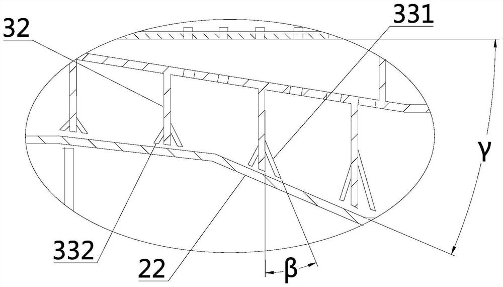
[0014] In the present invention, the guide surface corresponding to the tapered section refers to the guide surface on the blocking plate on the stirring blade correspondingly matched with the tapered section, and similarly, the guide surface corresponding to the straight section refers to the stirring blade correspondingly matched with the straight section The guide surface on the stop piece on the top.

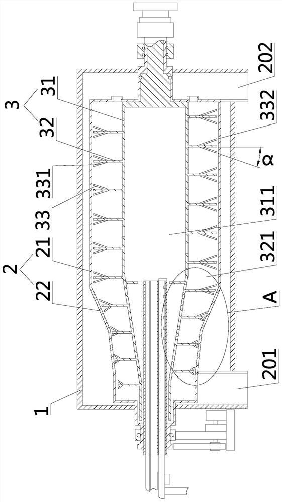
[0015] The invention provides a sludge dewatering device, such as figure 1 and figure 2 As shown, it includes a casing 1, a rotating cylinder 2 set inside the casing 1, and a stirring frame 3 set inside the rotating cylinder 2. The stirring frame 3 includes a main body 31 and stirring blades 32. The inside of the main body 31 is provided with a sludge injection The supply chamber 311, the stirring blade 32 and the rotating cylinder 2 form a separation chamber 321 communicating with the supply chamber 311, and the two ends of the rotating cylinder 2 are respectively provide...


PUM


Abstract

The invention discloses a sludge dewatering device, which solves the problems of low dehydration efficiency and separation discharge efficiency. The technical solution to solve the problem mainly includes a casing, a rotating cylinder set inside the casing, and a rotating cylinder set inside the rotating cylinder. Stirring frame, the stirring frame includes a main body and stirring blades. The main body is provided with a supply chamber for sludge injection. The stirring blades and the rotating cylinder form a separation chamber connected with the supply chamber. The two ends of the rotating cylinder are respectively equipped with a separator outlet and a separation chamber liquid outlet, the rotating cylinder includes a straight section and a conical section, the conical section is closer to the separator outlet than the straight section, the large end of the conical section is connected to the straight section, a baffle plate is set on the stirring blade, and a baffle plate is set on the baffle plate. There is a guide surface that guides the sludge to slide towards the inner wall of the rotating cylinder. The end of the blocking plate away from the main body is provided with a cutting edge. The angle between the guide surface corresponding to the tapered section and the cross section of the rotating cylinder increases sequentially from the inside to the outside along the axial direction. The included angles between the guide surface corresponding to the straight section and the cross section of the rotary cylinder are all equal.

Description

technical field [0001] The invention relates to a sludge dewatering device. Background technique [0002] The sludge dehydration separation device uses centrifugal rotation to concentrate and dehydrate the sludge. In order to improve the performance of concentration and dehydration, two coagulants (inorganic coagulant and polymer coagulant) are generally mixed into the sludge, which not only reduces the dewatering pollution The water content of the mud is increased, and the clarity of the dehydration separation liquid is increased. The inorganic coagulant is injected into the sludge and mixed with more sludge with the continuous stirring of the stirring blades. However, during the continuous stirring of the stirring blades, the sludge will also Continuously move to the separator outlet and finally discharge, so the time for the inorganic coagulant and sludge to be stirred and mixed is limited, and it is impossible to ensure that the inorganic coagulant and sludge are evenly ...

Claims


Application Information

Patent Timeline
Patent Type & Authority Patents(China)
IPC IPC(8): C02F11/127C02F11/143
CPCC02F11/127C02F11/14
Inventor 张志良
Owner 平湖市万顺达机械有限公司
Why Eureka
Try Eureka