Diaphragm Damper Device, Holding Member Therefor, And Production Method For Diaphragm Damper Device

一种保持部件、阻尼器的技术,应用在弹簧/减振器制造、燃料喷射装置、减振器等方向,能够解决制造装置复杂大型化等问题

Active Publication Date: 2018-02-16
EAGLE INDS
View PDF6 Cites 4 Cited by
  • Summary
  • Abstract
  • Description
  • Claims
  • Application Information

AI Technical Summary

Problems solved by technology

[0006] In this way, in the conventional damper device, it is necessary to simultaneously hold and move all the diaphragms of the two diaphragm dampers 51, 55 and to introduce and weld gas, so the manufacturing device is complicated and enlarged.

Method used


Image

  • Diaphragm Damper Device, Holding Member Therefor, And Production Method For Diaphragm Damper Device
  • Diaphragm Damper Device, Holding Member Therefor, And Production Method For Diaphragm Damper Device
  • Diaphragm Damper Device, Holding Member Therefor, And Production Method For Diaphragm Damper Device

Examples


Embodiment 1

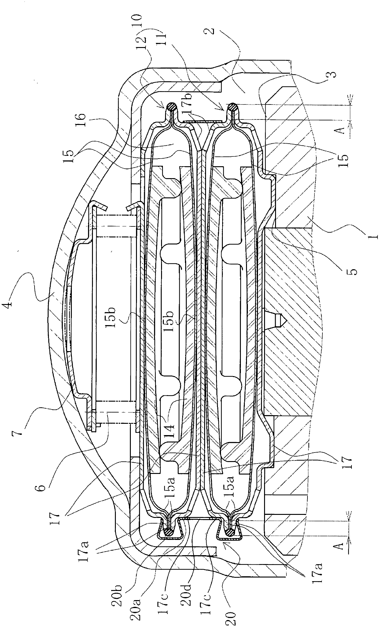
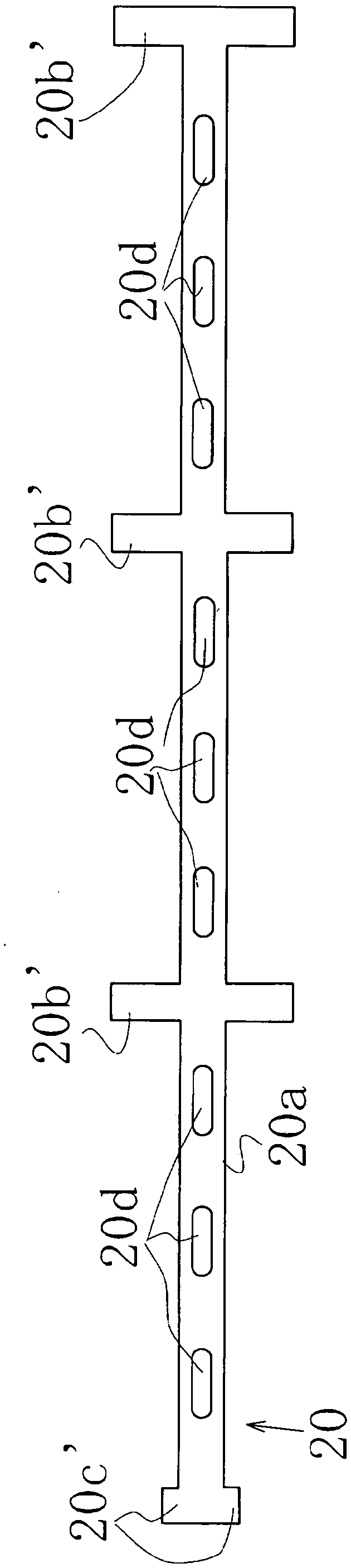
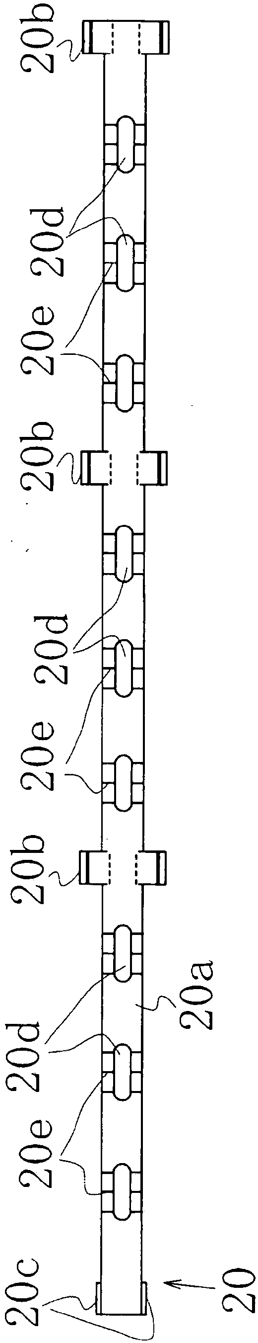
[0037] refer to Figure 1 to Figure 5 , the diaphragm damper device 10 and the holding member 20 provided in the diaphragm damper device 10 according to Embodiment 1 of the present invention will be described.

[0038] figure 1 The illustrated diaphragm damper device 10 is used in a high-pressure pump that pressurizes fuel supplied from a fuel tank and pressurizes it toward an injector by reciprocating a plunger.

[0039]The high-pressure pump has a fuel chamber 2 that can accommodate fuel supplied from the outside, and pressurizes and discharges the fuel by repeating the "suction process", "quantity adjustment process" and "pressurization process". When the plunger descends, it sucks fuel from the fuel chamber 2 to the pressurized chamber. When the plunger rises, part of the fuel in the pressurized chamber returns to the fuel chamber 2 in the "adjustment process". After the suction valve is closed, the "pressurization process" Fuel is pressurized as the plug rises further....


PUM


Abstract

A holding member for a diaphragm damper device comprising a plurality of diaphragm dampers is formed from an elastic material and comprises: a band section to which the side perimeter of the pluralityof diaphragm dampers can be elastically fastened; and hook sections provided on both sides of the band section. The hook sections elastically sandwich each of the plurality of diaphragm dampers thathave been arranged overlapping.

Description

technical field [0001] The present invention relates to a diaphragm damper device for absorbing pulsation, a holding member thereof, and a method of manufacturing the diaphragm damper device, which is used, for example, at a site where pulsation occurs in a high-pressure fuel pump or the like. Background technique [0002] As a conventional device for absorbing such pulsation, for example, a diaphragm damper device provided in a fluid passage of a high-pressure fuel pump is known (hereinafter referred to as "prior art". For example, refer to Patent Document 1). In this prior art, the damper device provided in the fluid passage of the high-pressure fuel pump absorbs pressure pulsation of fuel discharged from the high-pressure fuel pump, reduces the width of fuel pressure pulsation, and stabilizes the fuel injection amount. [0003] In this prior art diaphragm damper device, in order to increase the reduction effect of the pressure pulsation of the fuel, as Figure 7 As shown,...

Claims


Application Information

Patent Timeline
Patent Type & Authority Applications(China)
IPC IPC(8): F16F9/04F02M55/00F02M59/44F16B2/08F16F15/023
CPCF02M55/04F02M59/44F16B2/08F16F9/04F16F15/023F16F9/0454F16F9/049F16F2222/126F16F2226/04
Inventor 岩俊昭小川义博藤原靖佐藤裕亮
Owner EAGLE INDS
Why Eureka
Try Eureka