
Method for the production of a bladder accumulator and bladder accumulator produced according to said method

A technology of airbag accumulators and accumulators, applied in the direction of accumulator devices, actuator accumulators, outer walls of container structures, etc., can solve problems such as unavoidable different structures

Active Publication Date: 2018-02-16
HYDAC TECH GMBH
View PDF9 Cites 7 Cited by
  • Summary
  • Abstract
  • Description
  • Claims
  • Application Information

AI Technical Summary

Problems solved by technology

In view of the differently dimensioned valve openings in the accumulator housing, the subsequently applied wraps are inevitably designed differently, wherein each individual wrap is also in turn in the subsequent composite, especially in view of its walls. The diameters have a different design, so that the fiber layer composite can be wound easily; however, it has disadvantages when introducing forces, especially when high strength values ​​are desired when viewed in the axial direction of the accumulator housing

Method used


Image

  • Method for the production of a bladder accumulator and bladder accumulator produced according to said method

Examples


Embodiment Construction

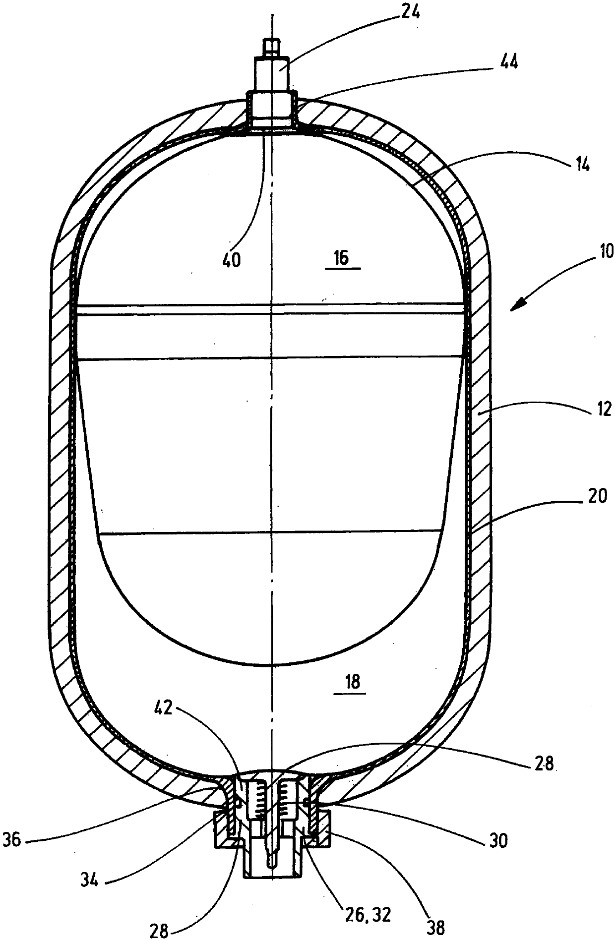
[0022] The bladder-type accumulator shown in the figure and generally designated 10 has an accumulator housing 12 which connects two medium chambers 16 , 18 by means of a bladder body 14 or accumulator bladder. separated from each other. The first medium chamber 16 of the bladder accumulator 10 is usually used to contain a working gas, such as nitrogen, and the second medium chamber 18 contains a liquid, such as hydraulic oil or the like. This means that the aforementioned medium chambers 16 , 18 correspond to the usual gas or liquid side of the bladder-type accumulator 10 .

[0023] The accumulator housing 12 is constructed in the form of a composite pressure vessel with an inner plastic core vessel 20 which is wound on the outer peripheral side with plastic fibers forming a plastic shell 22 . Instead of the plastic materials described for the plastic core container 20 and for the plastic outer shell 22 , metal materials such as aluminum, which can be easily formed and can a...


PUM


Abstract

The invention relates to a method for the production of a bladder accumulator (10) which separates two media chambers (16, 18) from one another in a storage housing (12) by means of a bladder body (14), comprising at least the following production steps: - extruding a plastic tube over the bladder body (14); - shaping the plastic tube with the integrated bladder body (14) in a molding tool that corresponds to a predeterminable plastic core container (20), and - winding at least one plastic fiber from the outside on the plastic core container (20) for the purpose of creating the storage housing(12).

Description

technical field [0001] The invention relates to a method for producing a bladder-type accumulator in which two medium chambers are separated from one another in an accumulator housing by means of a bladder body. The invention also relates to a bladder accumulator produced according to the method. Background technique [0002] A hydraulic accumulator, in particular in the form of a bladder accumulator, is known from DE 10 2006 004 120 A1 for receiving at least one fluid medium, which has a pressure vessel with a first plastic housing and a second plastic housing at least partially enclosing the first plastic housing, wherein the first plastic housing has a flange portion at least on one end thereof, the flange portion including means for controlling the medium supply and the medium discharge The valve opening, and the flange part and the second plastic housing are supported on an outer support ring located between them that tapers in a wedge shape towards the gap opening bet...

Claims


Application Information

Patent Timeline
Patent Type & Authority Applications(China)
IPC IPC(8): F15B1/16F17C1/16
CPCF15B1/16F17C1/16F17C2201/018F17C2201/0109F17C2203/0663F17C2203/066F17C2209/2127F17C2209/2154F17C2209/2145B29L2022/022B29L2022/02B29L2022/025B29L2031/7156B29C49/04F15B1/165B29C2049/2008B29C2049/2047F17C2201/0147F17C2203/018F17C2203/0604F17C2203/0619F17C2203/0673F17C2205/0305F17C2205/0323F17C2205/0394F17C2250/043F17C2250/0439F17C2250/0447F17C2260/036F15B2201/61F17C2221/014B29D22/02F15B2201/3152F15B2201/4053F15B2201/4155F15B2201/615B29D22/003B29C49/041
Inventor P·克洛夫特H·巴尔特斯
Owner HYDAC TECH GMBH
Learn More