
Local dynamic path planning method for mobile robot based on adaptive dynamic window

A mobile robot and dynamic window technology, applied in the direction of instruments, non-electric variable control, two-dimensional position/channel control, etc., can solve the problems of insufficient smoothness of robot trajectory, reduced safety and comfort, and prone to collisions, etc., to achieve The effect of reducing the number of running steps and running time, ensuring high speed and safety, and smooth running trajectory

Active Publication Date: 2018-02-16
UNIV OF SHANGHAI FOR SCI & TECH
View PDF9 Cites 38 Cited by
  • Summary
  • Abstract
  • Description
  • Claims
  • Application Information

AI Technical Summary

Problems solved by technology

However, the existing DWA methods still have the following problems: 1. For complex environments, the trajectory obtained by the robot is not smooth enough. In areas with dense obstacles, the robot may not choose a short path to pass through the dense area, but bypass the dense area. 2. When the speed weight in the DWA objective function is large, when the robot passes through the middle of two obstacles or a narrow passage, the robot is too close to an obstacle. If it is a pedestrian or a moving object, it is easy to Collisions lead to a significant reduction in safety and comfort; when the speed weight is small, the path is safe and reasonable, but the speed of the entire trip is significantly lower, and the overall running time becomes longer

Method used


Image

  • Local dynamic path planning method for mobile robot based on adaptive dynamic window
  • Local dynamic path planning method for mobile robot based on adaptive dynamic window
  • Local dynamic path planning method for mobile robot based on adaptive dynamic window

Examples


Embodiment 1

[0077] Embodiment 1: Objective function optimization

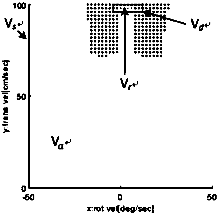
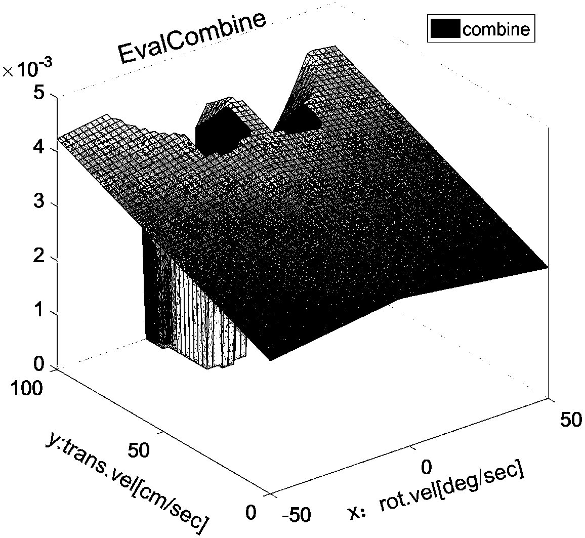
[0078] Fig. 2(a) is a schematic diagram of velocity space in Embodiment 1 of the present invention, and Fig. 2(b) is a 3D diagram of the objective function when acceleration constraints are ignored in Embodiment 1 of the present invention.

[0079] In order to obtain the optimal speed at time t+1, firstly normalize the three inputs heading, dist, and vel respectively, and then filter out the optimal speed at time t+1 through the objective function G(v,ω).

[0080] In order to ensure the entire objective function, it is assumed that the acceleration of the mobile robot at time t can be from 0 to arbitrarily large, the linear velocity is [0, 100], and the angular velocity is [-50, 50]. In this case, we plot the acceleration at time t 3D objective function, as shown in Figure 2(b), at this time the mobile robot pose (x, y, θ) t = (4.6833, 5.7965, 0.6807), velocity (v, ω) t =(100,4). Comparing the velocity space diagram in ...

Embodiment 2

[0082] Example 2: Verify the influence of the distance between the mobile robot and the obstacle on the speed optimization when the weight of the speed item γ is a low weight

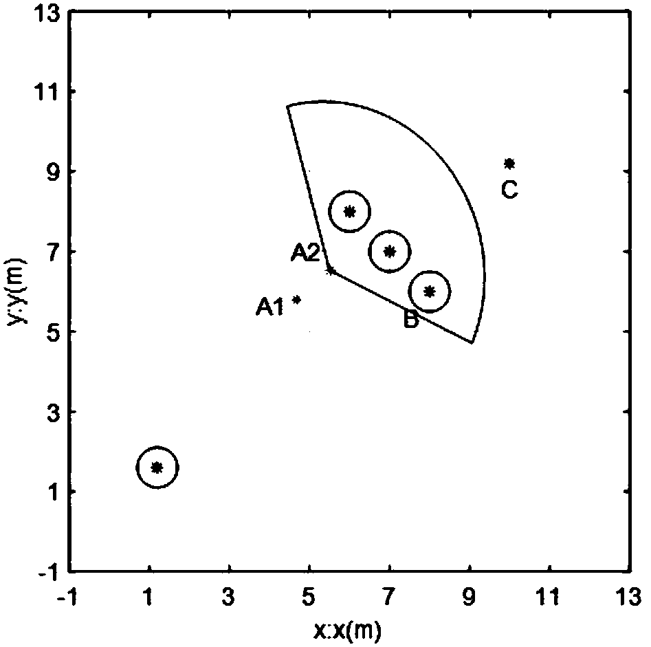
[0083] figure 1 It is the experimental simulation environment map in the embodiment of the present invention, and Fig. 3 (a) is the 3D schematic diagram of objective function when the mobile robot is far away from the obstacle in the embodiment of the present invention; Fig. 3 (b) is the implementation of the present invention The 3D diagram of the objective function when the mobile robot in the second embodiment is closer to the obstacle in the example.

[0084] Fig. 3 (a) is the 3D schematic diagram of the objective function when the mobile robot in the second embodiment of the present invention is far away from the obstacle, Fig. 3 (b) is the mobile robot in the second embodiment of the present invention is far away from the obstacle 3D plot of the near-time objective function.

[0085] When the mo...

Embodiment 3

[0087] Example 3: Speed ​​Weight γ High Time Original DWA Optimization Experiment

[0088] Fig. 4 (a) is the 3D figure of objective function when the mobile robot in the embodiment three in the embodiment of the present invention is far away from the obstacle, Fig. 4 (b) is the mobile robot in the embodiment three in the embodiment of the present invention is far away from the obstacle 3D plot of the objective function when obstacles are close.

[0089] When the mobile robot is far away from the obstacle at time t, such as figure 1 A in 1 , γ=20, mobile robot pose (x, y, θ) t = (4.6833, 5.7965, 0.6807), velocity (v, ω) t = (100, 4), the objective function obtained by DWA is shown in Figure 4(a). The optimal speed at time t+1 after optimization is (100, 4), namely v t+1 =v t , which is also the maximum linear speed of the mobile robot. It can be concluded that when the velocity weight γ is high and the mobile robot is closer to the obstacle, the optimal linear velocity a...


PUM


Abstract

The invention discloses a local dynamic path planning method for a mobile robot based on an adaptive dynamic window, and the method comprises the following steps: calculating a dynamic range thresholdvalue D<scale>; judging whether the mobile robot enters a dense barrier region or not; calculating a dynamic weight value gamma<d> of a linear speed v when the mobile robot is judged to enter the dense barrier region; calculating the interval Int<ij> of barriers, and judging whether the mobile robot can get across the dense barrier region or not; searching a standby speed space when the mobile robot can get across the dense barrier region, and obtaining an allowed speed (v, omega) when no collision happens; carrying out the normalization of three inputs (heading, dist and vel) of a target function, substituting the dynamic weight value gamma<d> and the allowed speed (v, omega) into the target function, obtaining an optimal speed combination (v<t+1>, omega<t+1>) through the target function, and enabling the optimal speed combination (v<t+1>, omega<t+1>) to serve as the moving speed of the mobile robot at a moment (t+1); executing the optimal speed, and judging whether the mobile robotarrives a target point or not: stopping the mobile robot if the mobile robot arrives the target point, or else switching to step 1 for a new loop.

Description

technical field [0001] The invention relates to a local dynamic environment obstacle avoidance method, in particular to a local dynamic path planning method for a mobile robot based on an adaptive dynamic window. Background technique [0002] Autonomous navigation is one of the necessary core technologies for mobile robots. In actual environments, especially in complex environments where humans and machines coexist, robots can obtain rough map information of the environment. However, due to the presence of moving objects, people or other variable factors, therefore, It is difficult to obtain complete information on the environment. When the local map information is known, the local dynamic path planning method is the preferred method to realize the autonomous navigation of intelligent robots. [0003] The simplest idea is to move along the line connecting the starting point and the target point. When an obstacle is encountered, it will go around along the edge of the obstac...

Claims


Application Information

Patent Timeline
Patent Type & Authority Applications(China)
IPC IPC(8): G05D1/02
CPCG05D1/0214G05D1/0221
Inventor 王永雄田永永李梁华魏国亮
Owner UNIV OF SHANGHAI FOR SCI & TECH
Learn More