
Calibrating test bench for thin oil film detection with ultrasonic wave

A technology of ultrasonic wave and thin oil film, which is applied in the direction of using ultrasonic wave/sonic wave/infrasonic wave, measuring device, instrument, etc., to achieve the effect of diverse device measurement, stable device structure and precise adjustment

Inactive Publication Date: 2018-02-16
HARBIN ENG UNIV
View PDF10 Cites 4 Cited by
  • Summary
  • Abstract
  • Description
  • Claims
  • Application Information

AI Technical Summary

Problems solved by technology

[0013] Although the device used in the above-mentioned measurement method can measure the thickness of the oil film more accurately, it still has certain limitations.

Method used


Image

  • Calibrating test bench for thin oil film detection with ultrasonic wave

Examples


Embodiment Construction

[0023] The present invention is described in more detail below in conjunction with accompanying drawing example:

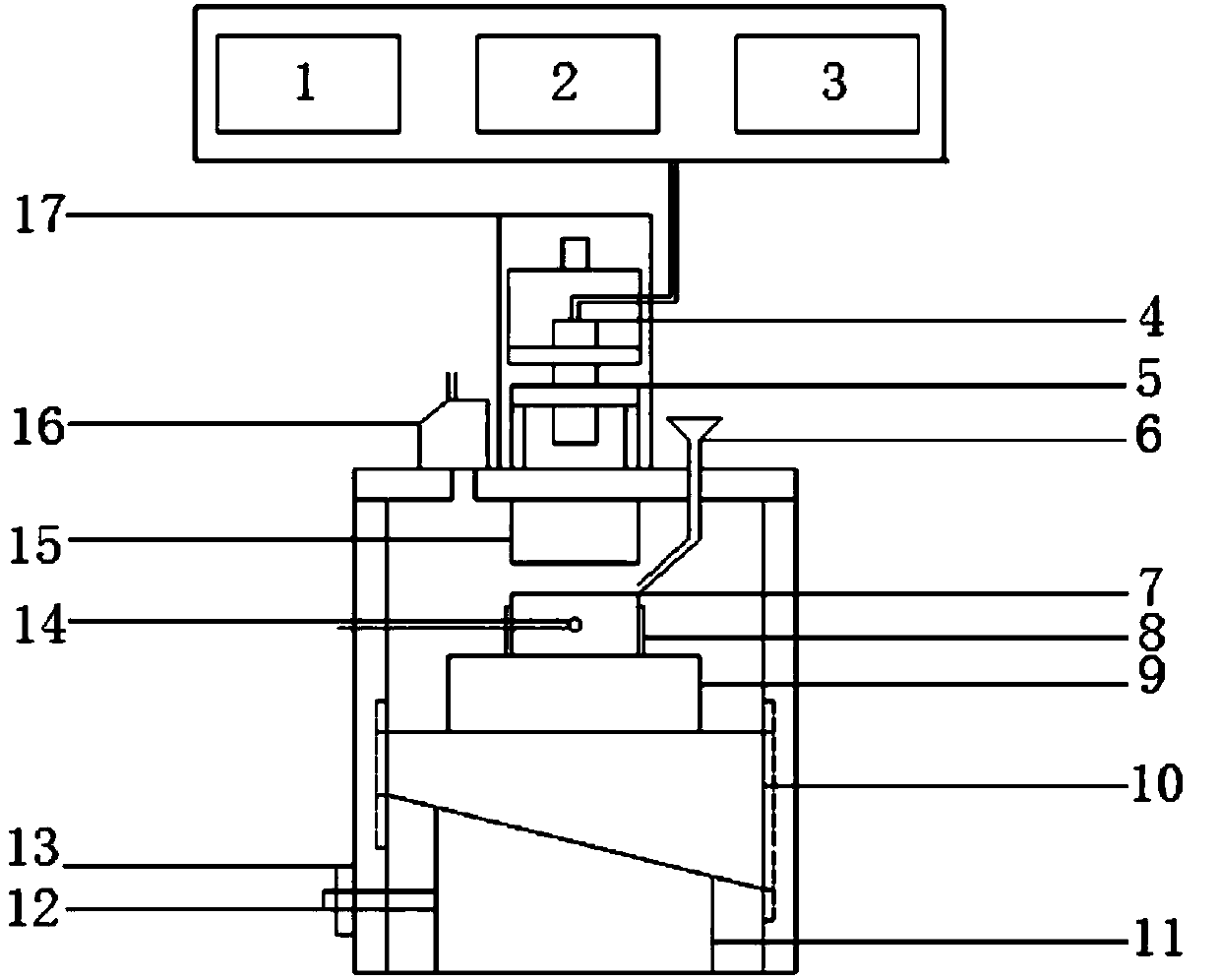
[0024] combine figure 1 , a calibration test bench for measuring the thickness of thin oil film by ultrasonic wave of the present invention, comprising ultrasonic transmitting and receiving devices 1, 2, water immersion type ultrasonic probe 4, water tank 5, bench, oil film upper block 15, oil film lower block 7, platform 9 , displacement sensor 16, platform adjustment 17, upper wedge 10, lower wedge 11, screw rod, nut 13 and other components. The probe is fixed on the upper plane of the water tank 5 . The ultrasonic emitting and receiving device includes: an ultrasonic emitting device 1 , an ultrasonic receiving device 2 and a computer 3 . Screw rod is fixed together with lower wedge 11 left ends. Block 7 under the oil film can be heated.

[0025] The rotation of the screw pushes the lower wedge 11 to move laterally, so that the height of the upper wedge 10 c...


PUM


Abstract

The purpose of the present invention is to provide a calibrating test bench for thin oil film detection with the ultrasonic wave. An adjusting platform is fixed above a stand, a water tank is locatedinside the adjusting platform, the inner wall of the top of the stand is fixed with an oil film upper block, an oil film lower block is arranged under the oil film upper block and is arranged on the platform, an upper wedge and a lower wedge are arranged under the platform in sequence, the inner wall of the side wall of the stand is provided with a side groove slideway, the upper wedge is providedwith a side rib, the inner wall of the bottom end of the stand is provided with a lower groove slideway, the lower wedge is provided with a lower rib, one side of the lower wedge is connected to a screw rod, the screw rod extends out of the stand and is connected to a nut, the wedged surface of the upper wedge and the wedged surface of the lower wedge are contacted, an ultrasonic probe is connected with an ultrasonic wave transmitting device and an ultrasonic wave receiving device, an ultrasonic transducer is installed on the adjusting platform, a laser displacement sensor is arranged on theupper surface of the stand, and the upper surface of the stand is notched. The displacement adjustment of the calibrating test bench is accurate, the required thickness can be conveniently obtained, and the minimum displacement can reach a level of 1 [mu]m.

Description

technical field [0001] The invention relates to a test bench for measuring oil film. Background technique [0002] Ultrasonic testing technology has the advantages of wide applicability, high flaw detection sensitivity, large detection depth, convenient use and good safety. It is currently one of the most widely used and most frequently used nondestructive testing technologies. At present, a large and excellent ultrasonic testing professional team and scientific research team have been established in China. The application scope of ultrasonic testing is expanding day by day. Related basic research and applied technology research are gradually deepening. Many achievements have reached or approached the foreign level. [0003] The research on ultrasonic detection technology first started abroad. In 1973, Tattersall H G used ultrasonic pulse echo technology to measure the thickness of the bonding layer, and established a spring model, thinking that when the middle layer is a t...

Claims


Application Information

Patent Timeline
Patent Type & Authority Applications(China)
IPC IPC(8): G01B17/02
CPCG01B17/02
Inventor 杨晓涛齐松博石勇
Owner HARBIN ENG UNIV
Learn More