Oil-water separator

A technology of oil-water separator and oil-water mixture, applied in liquid separation, separation method, centrifugal separation of water/sewage treatment, etc., can solve the problems of inability to separate small particles of oil residue, purification cannot be carried out normally, and the effect of purification is affected.

Pending Publication Date: 2018-02-16
黄守洪
View PDF0 Cites 0 Cited by
  • Summary
  • Abstract
  • Description
  • Claims
  • Application Information

AI Technical Summary

Problems solved by technology

The current oil-water separator cannot completely separate small particles of oil residue from the o...

Method used


Image

  • Oil-water separator
  • Oil-water separator
  • Oil-water separator

Examples


Embodiment Construction

[0028] The principles and features of the present invention are described below in conjunction with the accompanying drawings, and the examples given are only used to explain the present invention, and are not intended to limit the scope of the present invention.

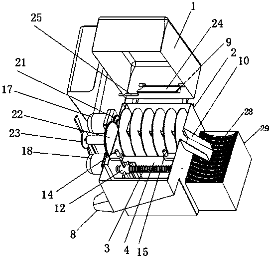
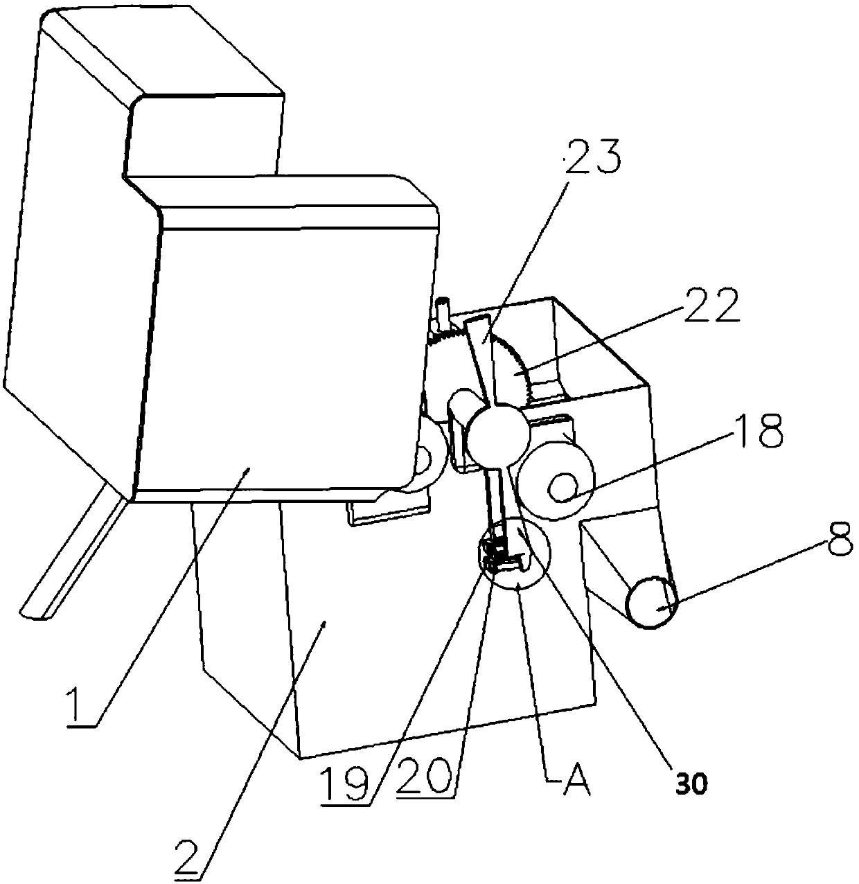
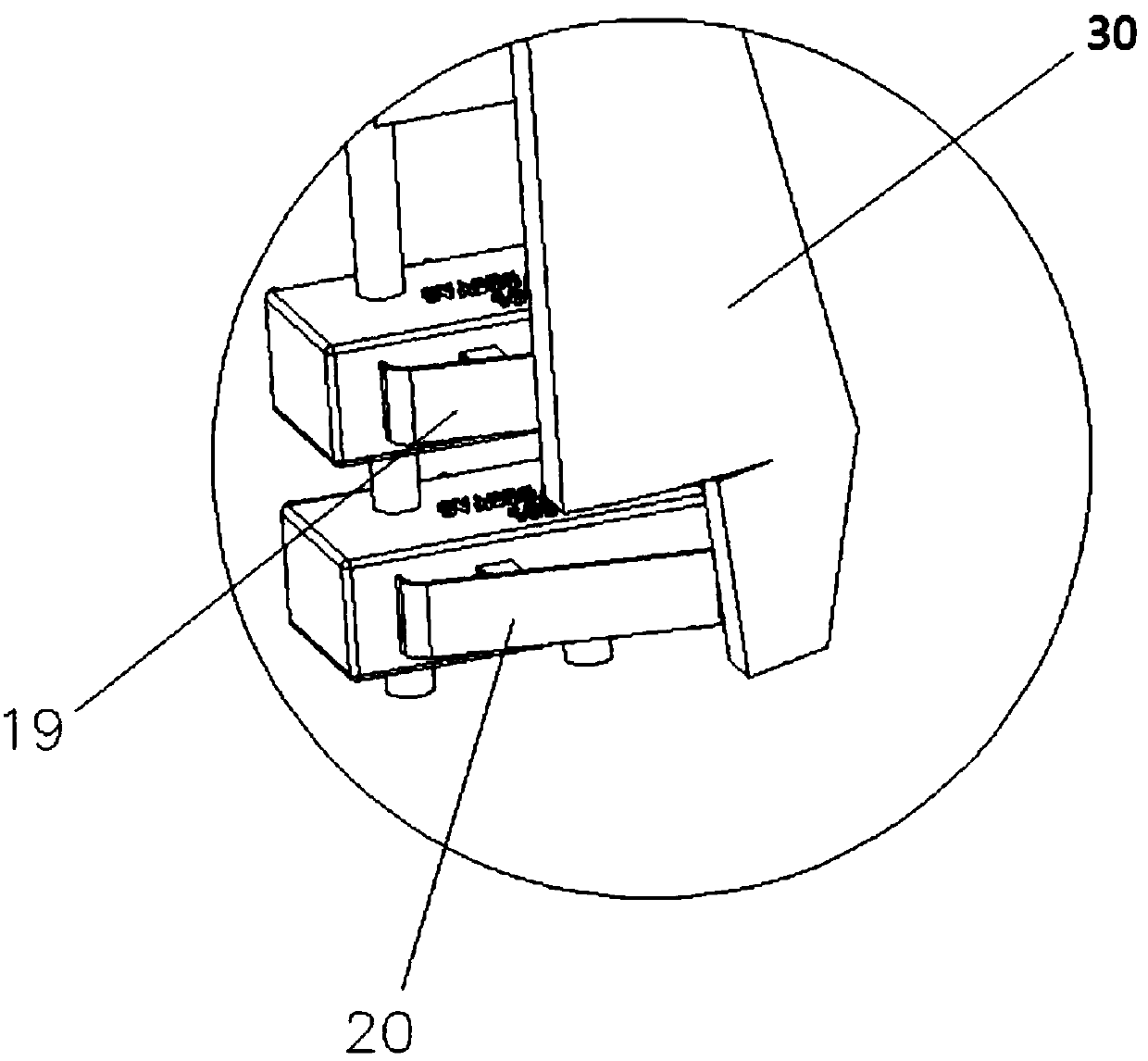
[0029] Such as Figure 1-3 Shown, a kind of oil-water separator, comprises box cover 1, box body 2 and screw rod 3; Described box cover 1 is covered on the top of described box body 2; There is a partition plate 4 with a gap at the bottom, and the partition plate 4 divides the inside of the box body 2 into a spiral groove 5 and a spoiler groove 6; the side of the spoiler groove 6 away from the spiral groove 5 is provided with a A water tank 7 connected to the launder 6, the water tank 7 is provided with a water outlet 8; an inlet 9 for injecting an oil-water mixture is provided on the top of the tank cover 1 corresponding to the spiral groove 5, and the tank cover 1 corresponds to the The position of the inlet 9 is...


PUM


Abstract

The invention relates to an oil-water separator, which comprises a case cover, a case body and a screw rod; a partition plate with a gap with the bottom of the case body is arranged in the case body, and the partition plate divides the part of the case body into a spiral groove and a spoiler tank; the side of the spoiler tank away from the spiral groove is provided with a water tank connected with the spoiler tank, and the water tank is provided with a water outlet; an inlet is provided on the box cover, and the spiral groove The top of the side wall is provided with an oil residue outlet, and a screen is provided in the spiral groove, and a spiral blade is arranged in the spiral groove; the screw rod is above the spoiler groove, and a There is a spoiler for agitating the tiny particles in the spiral groove and allowing the tiny particles to be discharged from the water outlet together with water. The oil-water separator can completely separate the oil and large particles of oil residue from the small particles of oil residue and water in the oil-water mixture, and complete the first step of purification of the oil-water mixture. The mixture of small particles of oil residue and water passes through a special sewage purification treatment plant Just deal with it.

Description

technical field [0001] The invention relates to the field of sewage treatment equipment, in particular to an oil-water separator. Background technique [0002] The oil-water mixture includes oil, large particle oil residue, small particle oil residue and water. The first step to purify the oil-water mixture is to separate the oil and large particle oil residue from the small particle oil residue and water in the oil-water mixture. into two parts. The current oil-water separator cannot completely separate small particles of oil residue from the oil-water mixture, resulting in the failure of subsequent purification or affecting the purification effect. Contents of the invention [0003] To sum up, in order to overcome the deficiencies of the prior art, the technical problem to be solved by the present invention is to provide an oil-water separator. [0004] The technical scheme of the present invention to solve the above-mentioned technical problems is as follows: an oil-w...

Claims


Application Information

Patent Timeline
IPC IPC(8): C02F1/00C02F1/38C02F1/40
CPCC02F1/001C02F1/38C02F1/40C02F2201/002C02F2301/04
Inventor 黄守洪
Owner 黄守洪
Why Eureka
Try Eureka