Electric vehicle drive control system and control method

A drive control and control method technology, applied in the field of electric vehicles, can solve problems such as failure to detect in time, endanger the safety of vehicles, waste of use costs, etc., and achieve the effects of improving the timeliness of protection, prolonging service life, and reducing use costs.

Active Publication Date: 2021-03-30
CHENGDU SIWI POWER ELECTRONICS TECH
View PDF6 Cites 0 Cited by
  • Summary
  • Abstract
  • Description
  • Claims
  • Application Information

AI Technical Summary

Problems solved by technology

However, there are still many technical bottlenecks restricting the industrialization and commercialization of low-speed electric vehicles. Among them, energy management technology is one of the prominent factors restricting the development of low-speed electric vehicles. The safe, efficient and stable operation of the drive control system is the key factor affecting the overall Key Factors in Performance
[0003] Due to application requirements, the drive control system is generally composed of multiple functional systems, which communicate with each other through the field bus and transmit information. However, the vehicle is generally in a state of high current during operation, and instantaneous state mutations are often caused by communication delays. It can be detected or judged in time to carry out protective treatment, causing serious faults and endangering vehicle safety
In addition, at present, the information of each functional system is not managed uniformly, so the vehicle cannot run in the best state, resulting in waste of use costs

Method used


Image

  • Electric vehicle drive control system and control method
  • Electric vehicle drive control system and control method

Examples


Embodiment Construction

[0023] The specific embodiments of the present invention are described below so that those skilled in the art can understand the present invention, but it should be clear that the present invention is not limited to the scope of the specific embodiments. For those of ordinary skill in the art, as long as various changes Within the spirit and scope of the present invention defined and determined by the appended claims, these changes are obvious, and all inventions and creations using the concept of the present invention are included in the protection list.

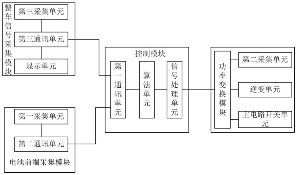
[0024] refer to figure 1 , figure 1 A schematic block diagram of the electric vehicle drive control system is shown. Such as figure 1 As shown, the electric vehicle drive control system includes a battery front-end acquisition module, a vehicle signal acquisition module and a power conversion module respectively connected to the control module.

[0025] The battery front-end acquisition module includes a second communica...


PUM


Abstract

The invention discloses an electric car driving controlling system and a controlling method thereof. The electric car driving controlling system comprises a battery front-end collecting module, a whole car signal collecting module and a power conversion module which are connected with a controlling module respectively; the battery front-end collecting module comprises a first collecting unit; thecontrolling module comprises a calculating unit and a first communication unit; the power conversion module comprises an inversion unit and a second collecting unit; the calculating unit is used for calculating the maximum current and the maximum power which can be output by battery sets currently, calculating the maximum output power of a power motor, calculating the maximum output power of an electric car and selecting the minimum value of the maximum power which can be output by batteries currently, the maximum output power of the power motor and the maximum output power of the electric caras the output power of the power conversion module; the output power of the power conversion module is adjusted to be a target output power according to set conditions.

Description

technical field [0001] The invention relates to electric vehicle technology, in particular to an electric vehicle drive control system and control method. Background technique [0002] Electric vehicles use electric energy as energy, and convert electric energy into mechanical energy through power motors. They are zero-pollution vehicles. As an important way to solve environmental pollution, they have developed rapidly in recent years. With the development of science and technology, especially new high-energy battery technology, the mileage of electric vehicles has been greatly improved, the charging time has been greatly shortened, and the cost has been greatly reduced. Electric vehicles have entered a new development period and have begun to enter the practical stage. . Among them, low-speed electric vehicles are developing most rapidly, with annual sales exceeding 1 million units. However, there are still many technical bottlenecks restricting the industrialization and ...

Claims


Application Information

Patent Timeline
Patent Type & Authority Patents(China)
IPC IPC(8): B60L15/20B60L58/10B60R16/023
CPCB60L15/20B60R16/023B60L58/10Y02T10/70Y02T10/72
Inventor 任亚辉纪小龙罗文谭志刚王浩洋
Owner CHENGDU SIWI POWER ELECTRONICS TECH
Why Eureka
Try Eureka